Systems and methods for fault-based power signal interruption

Inactive Publication Date: 2005-01-27
TDG AEROSPACE
View PDF7 Cites 76 Cited by
  • Summary
  • Abstract
  • Description
  • Claims
  • Application Information

AI Technical Summary

Benefits of technology

[0011] In an aircraft, for example, the circuitry of the present invention can protect systems both while an airplane is in the air and when it is on the ground. More specifically in the aviation field, such fault interrupter circuitry may advantageously assist aircraft manufacturers and airlines in complying with Federal Aviation Administration requirements such as SFAR 88, which requires the use of safety systems that do not impact the fuel system of the aircraft. The invention also provides a cost-effective

Problems solved by technology

When a fault occurs that has no current escaping to ground, the current may be escaping to another line or the impedance of the load may change dramatically resulting in an over-heated condition in the wiring.
For example, a fault in an aircraft can

Method used


Image

  • Systems and methods for fault-based power signal interruption
  • Systems and methods for fault-based power signal interruption
  • Systems and methods for fault-based power signal interruption

Examples


Embodiment Construction

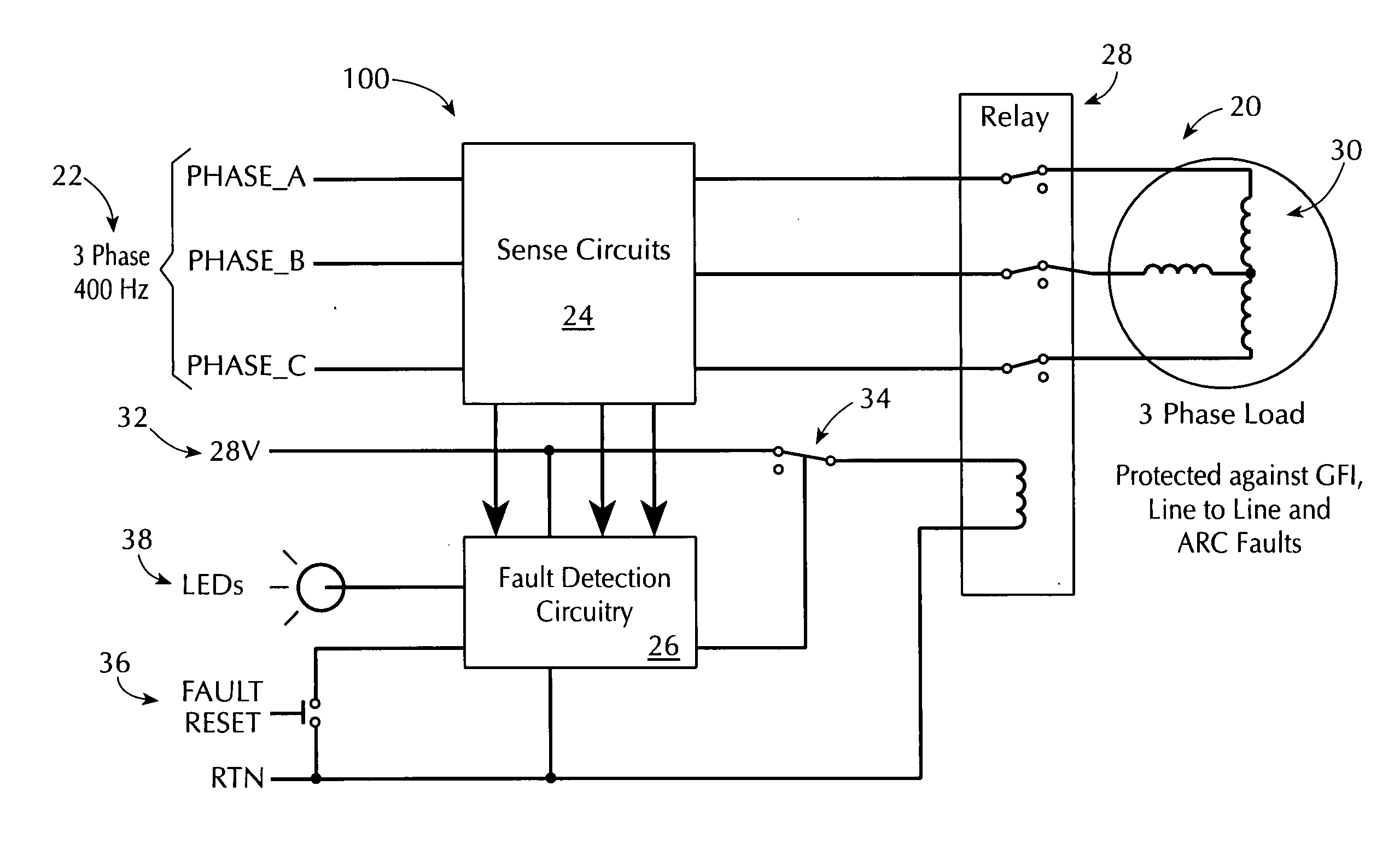
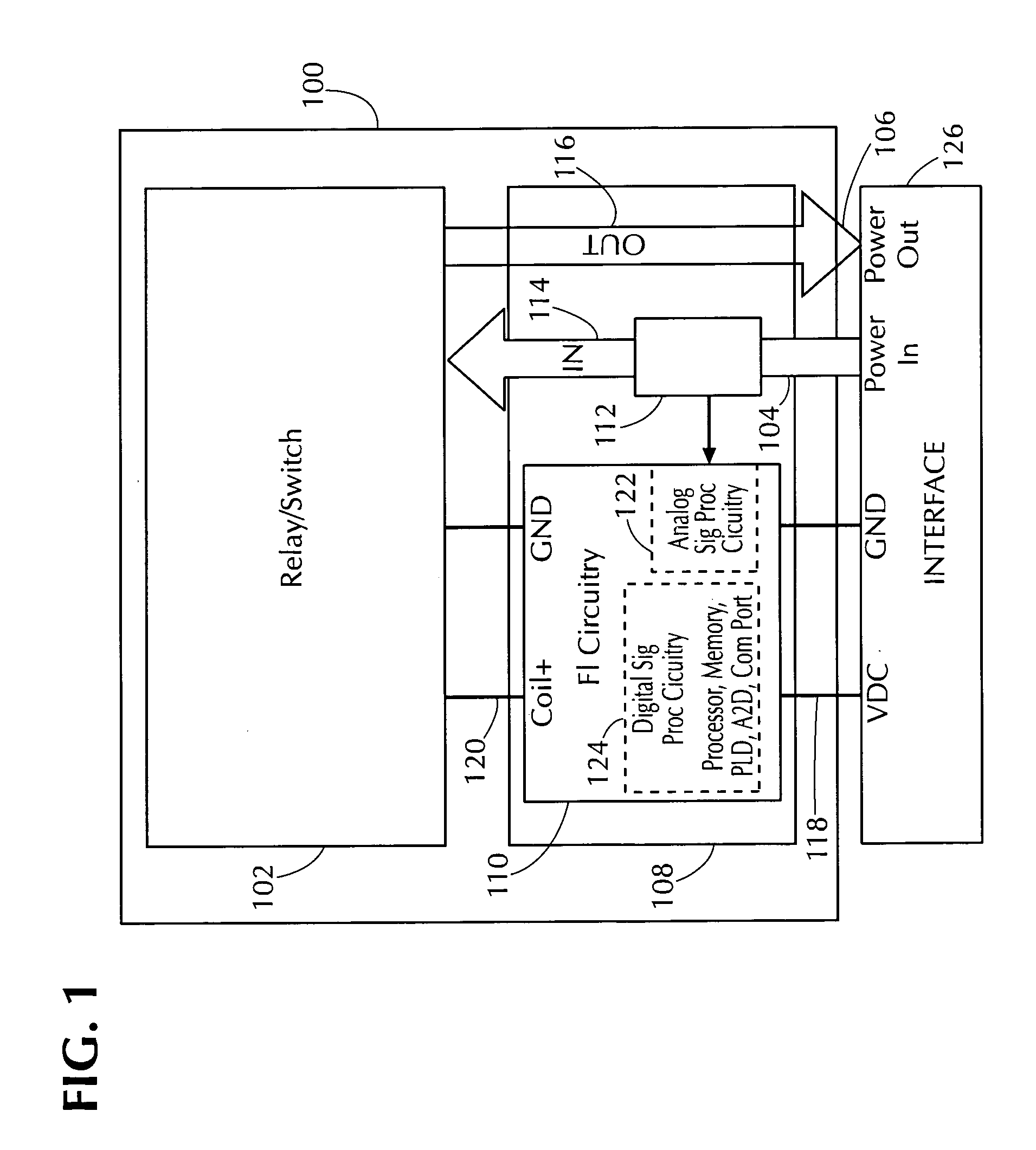
[0031]FIG. 1 is a functional block diagram of an illustrative power fault protection apparatus 100 for interrupting the supply of power in response to a power signal fault condition in accordance to a preferred embodiment of the present invention. Apparatus 100 includes relay or switch 102 (hereinafter, relay 102) to connect electrical signals on power-in conductors 104 to power-out conductors 106. Relay 102 can include relay or switch circuitry that can be actuated to controllably pass power signals through relay 102. Relay or switch circuitry of relay 102 should have sufficient capabilities to handle the intended power load. Such circuitry can include relays (e.g., relays used in aerospace electrical systems to channel power to subsystems such as boost pumps), contactors, or other types of switching circuitry such as semiconductor switching circuitry (e.g., solid state switches). Such circuitry can also include additional circuitry such as a coil or transformer for actuating a rel...


PUM


Abstract

Systems, methods, and apparatus for fault detection and interruption in power lines are provided. Circuitry is implemented via software and hardware that is configured to sense an operational aspect of a power line and apply signal processing to the sensed operational aspect to detect faults including different types of faults such as transient and steady state faults and can also be configured to identify the type of fault. Information on the fault and the identification of the type of fault can be displayed, stored, or some other output operation can be implemented. Circuitry can be implemented to provide digital signal processing and analog signal processing to, for example, independently and in parallel (e.g., redundant operation) detect faults and respond to faults as they occur (i.e., in real time). The types of faults can include transient type faults that can include ground, arc, line-to-line, and imbalance type faults and can also include steady state type faults (e.g., those showing wear in the machinery of a load).

Description

CROSS-REFERENCE TO RELATED PATENT APPLICATIONS [0001] This application claims the benefit of U.S. Provisional Patent Application No. 60 / 478,599, filed Jun. 13, 2003, U.S. Provisional Patent Application No. 60 / 547,099, filed Feb. 23, 2004, which are hereby incorporated by reference herein in their entirety.FIELD OF THE INVENTION [0002] The present invention relates to systems and methods for power signal interrupters and more particularly to interrupting or halting the supply of electrical power based on power signal fault conditions. BACKGROUND OF THE INVENTION [0003] Certain electrical systems suffer from wear and other types of physical deterioration through use or age. In aircrafts, for example, vibration, moisture, temperature extremes, and improper maintenance may contribute to failure of components in electrical systems, including wiring failures. Loose connections, broken, frayed, and / or exposed wires, may cause arcing which may be the source of electrical ignition in aircraf...

Claims


Application Information

Patent Timeline
IPC IPC(8): H02H3/00H02H3/04H02H3/08
CPCH01H2071/006H02H3/042H02H3/00H02H3/04
Inventor MLADENIK, JOHN E.EVANS, DAVID L.BARBA, JOSE M.LARSON, WAYNE L.FISH, DANIEL E.BENCH, GERALD
Owner TDG AEROSPACE
Why Eureka
Try Eureka