Continuous circuit and fuse protection in high voltage applications exposed to chemically harsh environments

a continuous circuit and fuse protection technology, applied in the direction of cell components, sustainable manufacturing/processing, batteries, etc., can solve the problems of one or more fuses being blown, the battery pack is in a compromised state, etc., to reduce or eliminate the chance of electrically corrupting other circuits, the effect of high resistance to flow

Active Publication Date: 2017-12-26
GM GLOBAL TECH OPERATIONS LLC
View PDF4 Cites 0 Cited by
  • Summary
  • Abstract
  • Description
  • Claims
  • Application Information

AI Technical Summary

Benefits of technology

[0008]In accordance with one aspect of the present invention, an assembly for sensing voltage produced by at least one battery cell within a battery pack is disclosed. The assembly includes a substrate with one or more voltage sensing circuits formed on its surface, where each such circuit includes a surface-mounted fuse (also referred to as a fusible element) that is electrically coupled to an electrically-conductive line or trace. In the present context, a surface-mounted fuse differs from an integrally-formed one through its method of fabrication. For example, the integrally-formed fuse is preferably formed by a patterning or related deposition process, whereas the discretely-formed surface-mounted version is first manufactured, then attached to the substrate through the aforementioned welding, soldering or related joining techniques. Likewise, a particular form of the substrate is as a battery interconnect board (ICB) which may have optional rigid (for example, a printed circuit board) or flexible circuit boards secured thereto. The Assignee of the present invention has found that an ICB-based approach to battery pack design provides a convenient, modular way to electrically connect numerous individual battery cells to one another within a module, as well as to other modules within the pack a way to further electrically connect the pack to the various electrical loads within the vehicle. Significantly, the coating protects the area between the pads and from the environment, which in turn permits the use of a smaller fuse and related greater space between circuits.
[0011]In accordance with yet another aspect of the present invention, a method of providing maintenance of coating integrity during fuse operation for an automotive propulsion system battery pack voltage sensing circuit is disclosed. The method includes coating at least one layer of a precursor onto the fuse of the voltage-sensing circuit such that the precursor substantially covers all exposed portions of the fuse that along with the remainder of the circuit is disposed on a substrate. The precursor is made from a thixotropic material; in this way, the relatively high resistance to flowing means that upon coating the precursor onto the fuse, it remains in place over a substantial entirety of the fuse, even at corners and related fuse locations where a fusing event is likely to cause a breach in the fuse's ceramic containment. Once the fuse has been coated, a curing step may be used on the precursor such that it hardens to form a substantially conformal encapsulant around the fuse. The encapsulant formed around the fuse maintains the fuse in substantial environmental isolation not only from the ambient environment during levels of the electrical current that correspond to both normal pack operation, as well as maintaining the coating integrity during fuse operation, thereby reducing or eliminating the chance of electrically corrupting other circuits.

Problems solved by technology

Moreover in the present context, the battery pack is in a compromised state when there is an event or condition that could jeopardize the proper operation of the pack, its voltage monitoring circuits or other key components.
One such compromised state is when a circuit-breaking episode occurs such that one or more of the fuses becomes blown.

Method used


Image

  • Continuous circuit and fuse protection in high voltage applications exposed to chemically harsh environments
  • Continuous circuit and fuse protection in high voltage applications exposed to chemically harsh environments
  • Continuous circuit and fuse protection in high voltage applications exposed to chemically harsh environments

Examples


Embodiment Construction

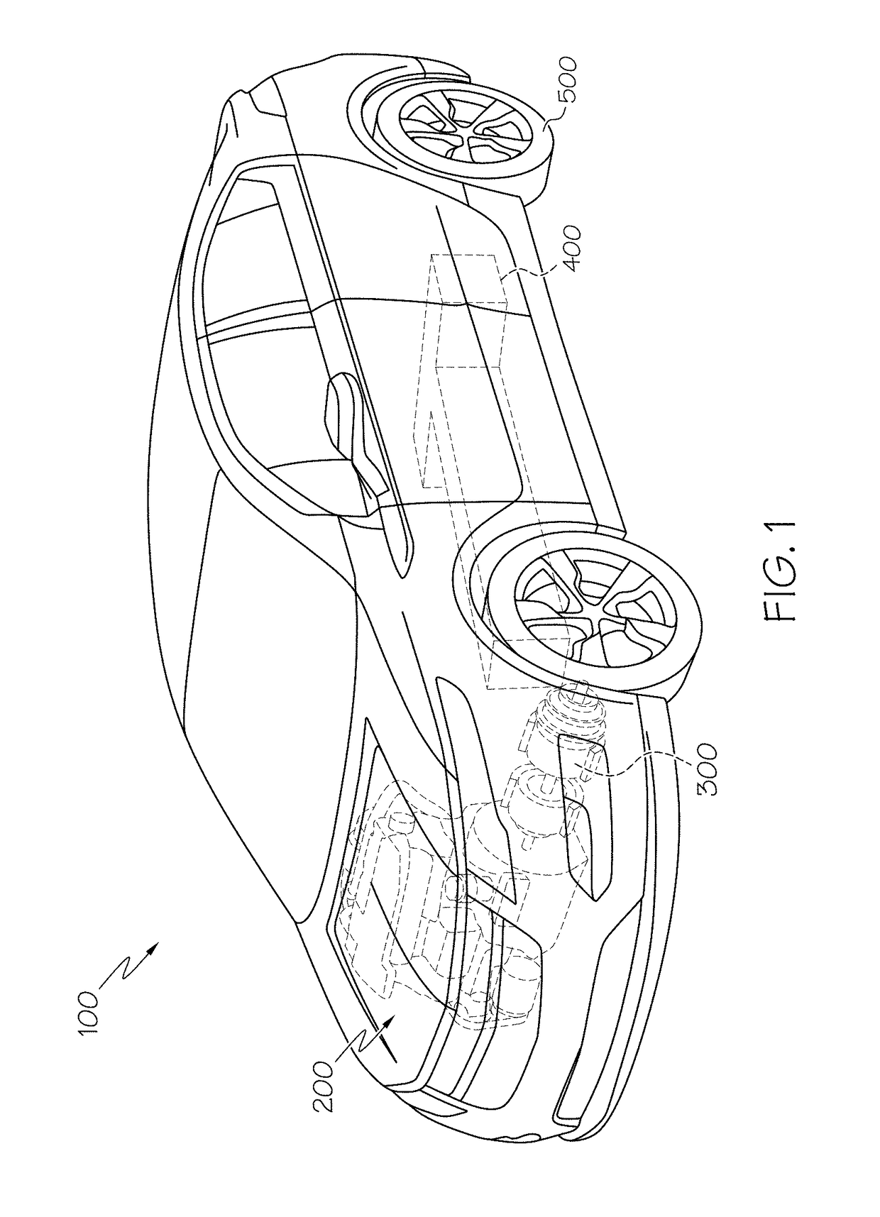
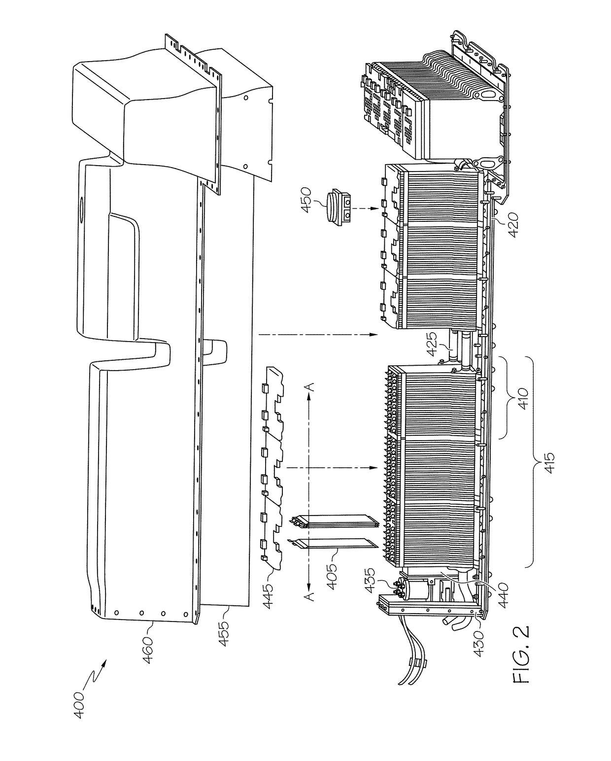
[0019]Referring first to FIGS. 1, and 2, views of a hybrid-powered vehicle 100 (FIG. 1) and a battery pack 400 (FIG. 2) used to propel vehicle 100 are shown. Within the present context, it will be appreciated that the term “vehicle” may apply to car, truck, van sport utility vehicle (SUV) or the like. In addition to the battery 400 (also referred to herein as battery pack to emphasize the assembled nature of multiple battery cells within), vehicle 100 includes an ICE 200, one or more electric motors 300 and as well as an electronic control system (not shown). Vehicle 100 further includes a powertrain (not shown, which could be in the form of a driveshaft or the like) to deliver propulsive power from the ICE 200, motor / generator 300 or battery 400 to one or more of the wheels 500. Battery 400 may additionally include a state of charge (SOC) system and power inverter assembly (neither of which are shown), the latter of which includes various modules, including those for the IGBT and c...


PUM

PropertyMeasurementUnit
thicknessaaaaaaaaaa
volume resistivityaaaaaaaaaa
dielectric strengthaaaaaaaaaa

Abstract

A battery pack, a device for sensing individual battery voltages in a battery pack and protecting the battery pack in the event of a circuit-breaking event, and a method for forming an encapsulant for the voltage-sensing circuit for use in a battery-powered automobile propulsion system. The battery pack includes numerous voltage sensing circuits with surface-mounted fuses and an encapsulant formed around each of the fuses. The encapsulant is robust enough to provide environmental isolation of the surface-mounted fuse such that the tendency of the fuse to form short-circuit connections to adjacent circuits is avoided under both normal battery pack operation and after a condition where the battery pack is compromised. The precursor to the encapsulant is made from a multiple layers of a traditional thin coating material or a single layer of a high-viscosity fluid to help maintain a minimum coating thickness around all exposed portions of the surface-mounted fuse, including the breech-prone corners.

Description

BACKGROUND OF THE INVENTION[0001]This invention relates generally to voltage-sensing and protective components used in conjunction with a battery-powered system, and more particularly to a way to increase the environmental resistance of a surface-mounted voltage-sensing fuse that is used as part of a voltage monitoring and protection circuit for multiple battery cells that are formed into a larger battery assembly such as that used for automotive propulsion.[0002]Lithium-ion and related batteries are being used in transportation applications as a way to supplement, in the case of hybrid electric vehicles (HEVs), or supplant, in the case of purely electric vehicles (EVs), conventional internal combustion engines (ICEs). The ability to passively store energy from stationary and portable sources, as well as from recaptured kinetic energy provided by the vehicle and its components, makes such batteries ideal to serve as part of a propulsion system for cars, trucks, buses, motorcycles an...

Claims


Application Information

Patent Timeline
Patent Type & Authority Patents(United States)
IPC IPC(8): H01M10/48H01M10/04H01M50/209H01M50/24H01M50/284H01M50/507H01M50/519H01M50/569
CPCH01M10/48H01M10/04H01M2220/20H01M10/425Y02E60/10H01M50/24Y02P70/50H01M50/507H01M50/519H01M50/209H01M50/284H01M50/569
Inventor SIU, CAMMI L.CELOTTO, MICHAEL A.
Owner GM GLOBAL TECH OPERATIONS LLC
Why Eureka
Try Eureka