Sound processing system for configuration of audio signals in a vehicle

a technology for configuration and sound processing, applied in the field of sound processing systems, can solve the problems of road noise, wind noise, and most home theater systems are not designed to operate with the added complexity of outside sounds, and achieve the effect of maximizing the frequency range of audio outpu

Inactive Publication Date: 2005-01-27
HARMAN INT IND INC
View PDF43 Cites 35 Cited by
  • Summary
  • Abstract
  • Description
  • Claims
  • Application Information

AI Technical Summary

Benefits of technology

[0011] This invention provides a sound processing system that includes a sound processor configured to mix real audio input signals to produce at least one virtual output signal on at least one virtual output channel. In addition, the sound processor is configured to produce real audio output signals on real audio output channels using at least one of the real audio input signals and the virtual output signal. The real audio output signals may be provided as an audio signal on an output signal line. The audio signals may be amplified and used to drive transducers, such as loudspeakers to produce an audio output that maximizes the frequency range of the audio output within a vehicle.

Problems solved by technology

Most home theater systems are not designed to operate with the added complexities inside of a vehicle.
The complexities include the complexity of outside sounds, such as road noise, wind noise, etc.
In addition, vehicle listening environments may have non-optimal loudspeaker placement coupled with loudspeakers with various frequency response ranges.
In contrast, it is nearly impossible in a vehicle to place each loudspeaker the same distance from the listeners when one considers the front and rear seating positions and their close proximity to the doors, as well as the kick-panels, dash, pillars, and other interior vehicle surfaces that could contain the loudspeakers.
These placement restrictions are problematic considering the short distances available in an automobile for sound to disperse before reaching the listeners.

Method used


Image

  • Sound processing system for configuration of audio signals in a vehicle
  • Sound processing system for configuration of audio signals in a vehicle
  • Sound processing system for configuration of audio signals in a vehicle

Examples


Embodiment Construction

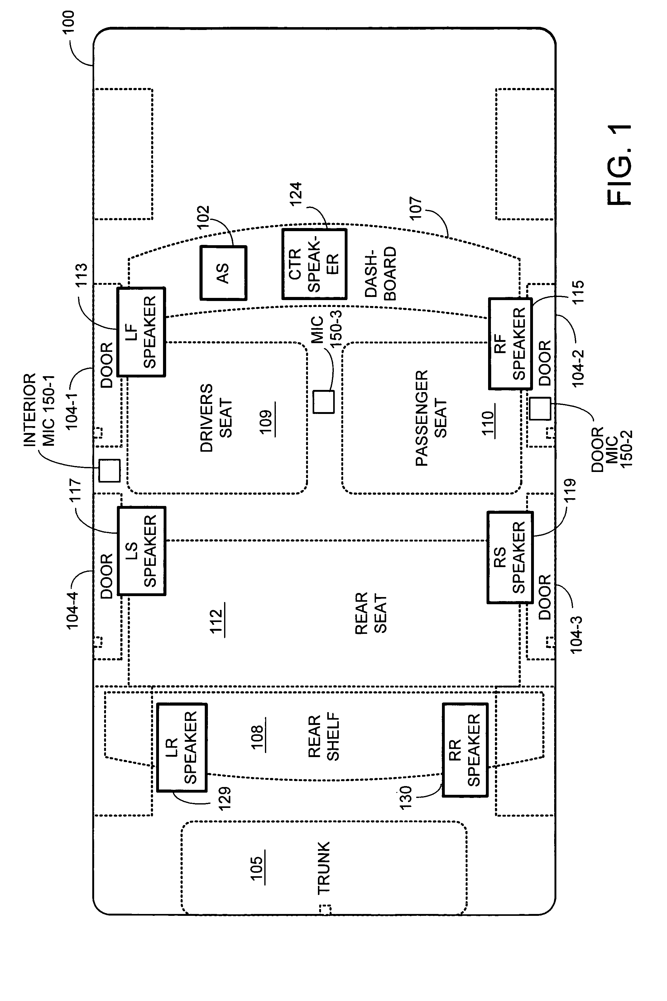
[0033]FIG. 1 is a block diagram of a vehicle 100 that includes an example audio or sound processing system (AS) 102, which may include any or a combination of the sound processing systems and methods described below. The vehicle 100 includes doors 104, a driver seat 109, a passenger seat 110, and a rear seat 111. While a four-door vehicle is shown including doors 104-1, 104-2, 104-3, and 104-4, the audio system (AS) 102 may be used in vehicles having more or fewer doors. The vehicle 100 may be an automobile, truck, boat, or the like. Although only one rear seat is shown, larger vehicles may have multiple rows of rear seats. Smaller vehicles may have only one or more seats. While a particular example configuration is shown, other configurations may be used including those with fewer or additional components.

[0034] The audio system 102 may improve the spatial characteristics of surround sound systems. The audio system 102 supports the use of a variety of audio components such as radi...


PUM


Abstract

A sound processing system for a vehicle includes a sound processor that is configured to mix at least one real audio input signal to form at least one virtual output signal. At least one audio signal that is available to drive at least one loudspeaker may be formed using the combination of the virtual output signal and the real audio input signal. The virtual output signal may be post processed to form a predetermined frequency range of the audio signal prior to being combined with the real audio input signal. The audio signal may be created by mixing the real audio input signal with the post processed virtual output signal. Alternatively, the audio signal may be formed by mixing the real audio input signal to form a real audio output signal, and then summing the real audio output signal with the post processed virtual output signal. Mixing may be performed with a crossbar mixer included in the sound processor.

Description

PRIORITY CLAIM [0001] The present patent document is a continuation-in-part of U.S. patent application Ser. No. 09 / 850,500, filed May 7, 2001. The disclosure of the above patent application is incorporated herein by reference.BACKGROUND OF THE INVENTION [0002] 1. Technical Field [0003] The invention generally relates to sound processing systems. More particularly, the invention relates to sound processing systems that configure audio signals to drive loudspeakers in a vehicle to maximize the frequency range of the audio output. [0004] 2. Related Art [0005] Audio or sound system designs involve the consideration of many different factors. The position and number of speakers, the frequency response of each speaker, and other factors usually are considered in the design. Some factors may be more pronounced in the design than others in various applications such as inside a vehicle. For example, the desired frequency response of a speaker located on an instrument panel of a vehicle usual...

Claims


Application Information

Patent Timeline
Patent Type & Authority Applications(United States)
IPC IPC(8): G06F17/50H04S3/02H04S5/00H04S5/02H04S7/00
CPCH04R2205/024H04R2499/13H04S3/02H04S7/40H04S7/00H04S7/307H04S5/005H04B1/00H04S5/00
Inventor FURGE, KENNETH CARLEID, BRADLEY F.SHIVELY, ROGER E.
Owner HARMAN INT IND INC
Why Eureka
Try Eureka