System and method for coupling and redirecting optical energy between two optical waveguides oriented at a predetermined angle

a technology of optical waveguides and coupling and redirection, applied in the field of optical structures, can solve the problems of splicing fiber optic cables that can be tedious and time-consuming, and can cause substantial losses in optical power at the splice, so as to maximize the collection and redirection of optical energy, minimize back reflection or other optical return losses, and maximize the effect of optical energy transfer

Inactive Publication Date: 2005-01-27
CYBER OPERATIONS
View PDF5 Cites 2 Cited by
  • Summary
  • Abstract
  • Description
  • Claims
  • Application Information

AI Technical Summary

Benefits of technology

[0029] The mirror of the optical coupler forms only a portion of the inventive optical system. The other parts of the optical system can comprise at least two lenses that are supported or precisely positioned by the two connectors. Each lens comprises an aspherically shaped lens that has a planar side and a convex side. The convex side of each aspherically shaped lens can have a prescription that maximizes the collection and redirection of optical energy. The prescription of each lens is a function of the optical coupler dimensions and a function of the optical waveguide dimensions and type.
[0030] Each convex side of each lens can face the inside of the connector housing, while each planar side of each lens can be positioned to face the optical waveguide. In this way, for a first aspherical lens, substantially all of the optical energy that exits a first optical waveguide in a dispersion cone of a predetermined angle can be collimated by the first aspherical lens and then redirected or reflected by the mirror.
[0031] The optical energy that is reflected from the mirror can be propagated into a second aspherical lens where the convex side of the second aspherical lens can focus the collimated optical energy into a focal point that can correspond directly with a central region of a second optical waveguide. The focused optical energy can then be propagated away from the second aspherical lens in the second optical waveguide. In this way, the optical coupler can maximize the optical energy transfer between two optical waveguides while minimizing any back reflection or other optical return losses. The optical coupler can maximize optical energy transfer between optical waveguides disposed at an angle by providing an automatic core-to-core alignment of optical waveguides in free space that is dependent on the precise positioning of the lenses in each connector, the position of the reflecting device in the housing, and the positions of each connector relative to the housing.

Problems solved by technology

Because the fiber optic cables extend over long distances, these cables usually encounter obstacles or redirection that are common with any utility line.
The splicing of fiber optic cables can be a tedious and time-consuming process.
If these human hair-like fiber optic cables are not properly aligned, substantial losses in optical power can occur at the splice.
Protecting splices with enclosures demonstrates that splicing of fiber optic cables can be a costly and time consuming process that does not guarantee optical coupling efficiency.
In addition to the problems associated with splicing, fiber optic cables cannot be bent at very large angles such as ninety degrees without suffering substantial optical power losses.
Micro-bending can cause greater losses at longer optical wavelengths, such as the optical wavelengths that support dense wavelength division multiplexing.
Another major drawback of larger bending techniques, in addition to the problems of stress and the amount of cable to perform the operation, is that such techniques require a substantial amount of space.
However, conventional optical connectors are usually permanent in nature, meaning that adjustments to the connector and any optics contained in the connector cannot be made during installation in the field.
Further, if any adjustments to the optics within the optical connector are necessary, such adjustments cannot be made in the field since the connectors are typically designed to permanently encase or house the optics contained therein.
Another drawback of conventional optical connectors is that very few of these conventional optical connectors can withstand the harsh operating environments of optical cables.

Method used


Image

  • System and method for coupling and redirecting optical energy between two optical waveguides oriented at a predetermined angle
  • System and method for coupling and redirecting optical energy between two optical waveguides oriented at a predetermined angle
  • System and method for coupling and redirecting optical energy between two optical waveguides oriented at a predetermined angle

Examples


Embodiment Construction

[0055] Referring now to the drawings, in which like numerals represent like elements throughout the several figures, aspects of the present invention in the illustrative operating environment will be described.

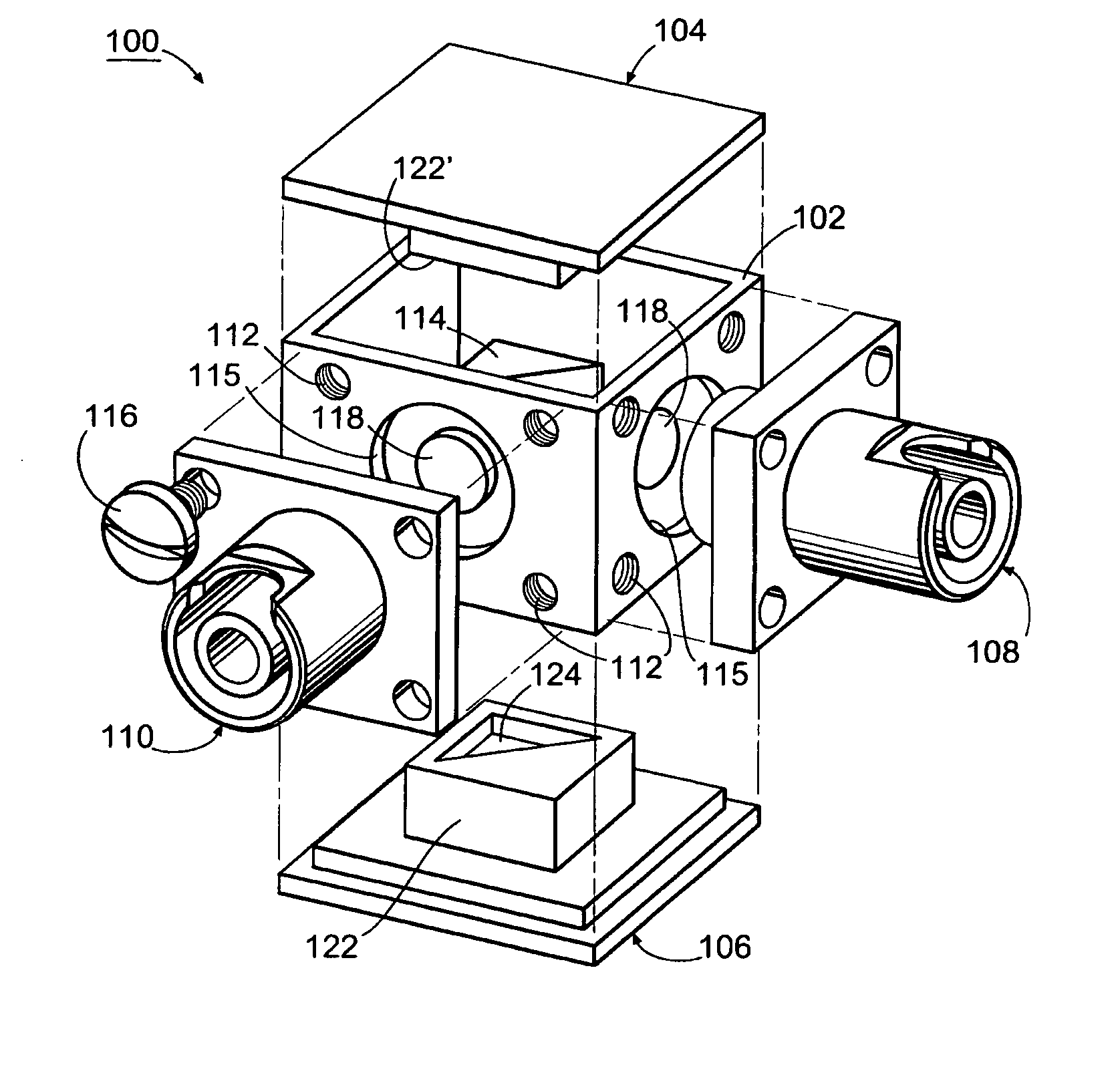
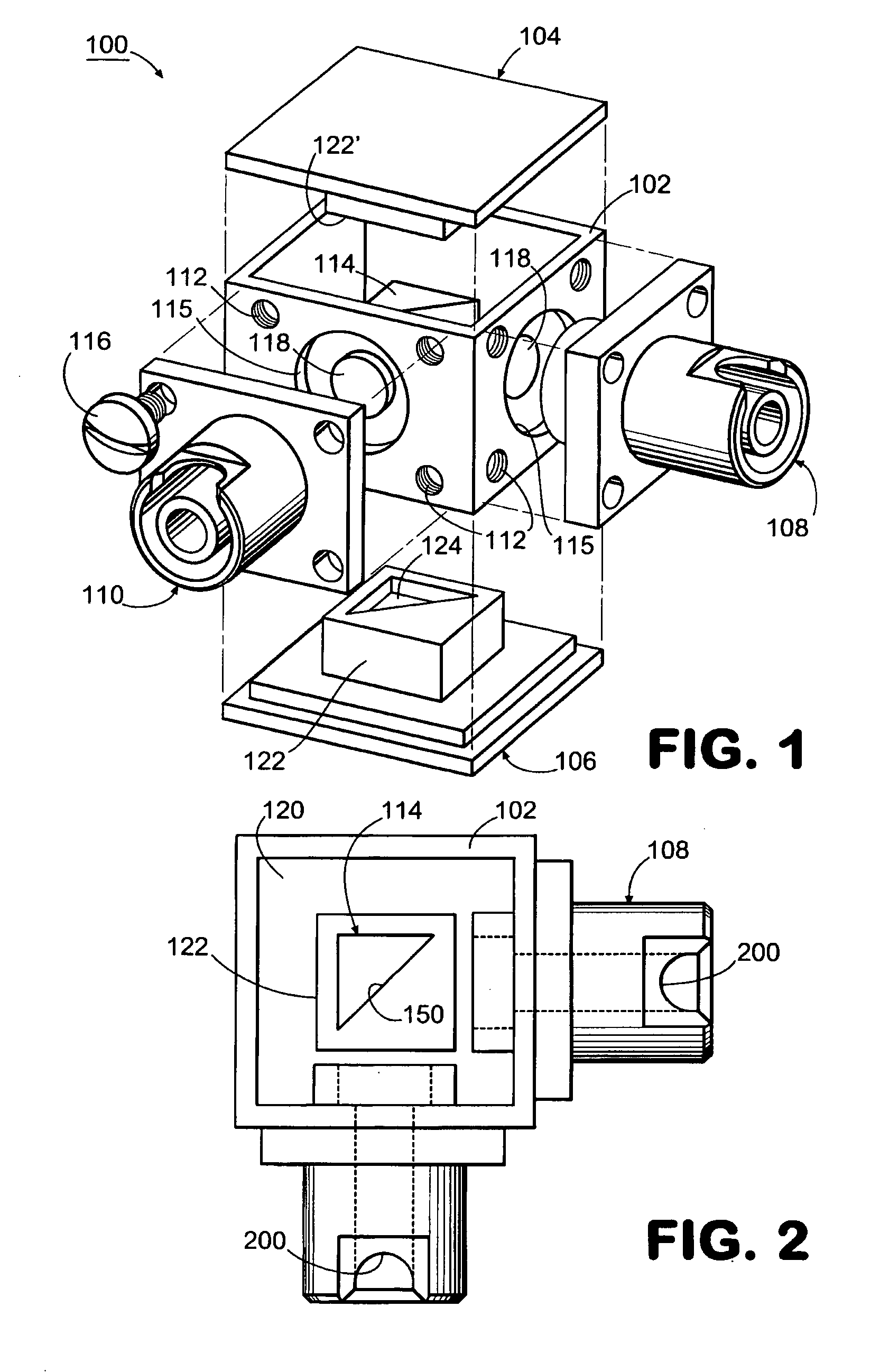
[0056]FIG. 1 is an assembly diagram of an exemplary optical coupler 100 according to the exemplary embodiment of the present invention. The optical coupler 100 can comprise a connector housing 102, a first cover 106, and a second cover 104. The optical coupler 100 may further comprise a first connector 108 and a second connector 110.

[0057] The connector housing 102 can take the form of a cubed-shaped structure. However, other shapes of the connector housing 102 are not beyond the scope of the present invention. For example, the connector housing 102 could take the form of a circular, triangular or rectangular shape. The connector housing 102 can be made from metal. Exemplary metals include, but are not limited to, steel, copper, nickel, or aluminum. The material for the conn...


PUM


Abstract

An optical waveguide coupler can be adjusted in the field and can couple and redirect optical energy leaving a first optical waveguide oriented in a first position into a second optical waveguide oriented in second position different from the first position. The optical coupler can maximize the optical energy transfer between two optical waveguides, while minimizing any back reflection or other optical return losses. The optical coupler provides an automatic core-to-core alignment of optical waveguides in free space by using aspherically shaped lenses with predetermined prescriptions in combination with a reflecting device that is accurately positioned between the two lenses.

Description

PRIORITY AND RELATED APPLICATIONS [0001] The present application claims priority to provisional patent application entitled “Right Angle Fiber Optic Cable Adapter,” filed Apr. 20, 2001 and assigned U.S. application Ser. No. 60 / 285,273. The entire contents of this provisional application are hereby incorporated by reference.TECHNICAL FIELD [0002] The present invention relates to optical structures. More specifically, the present invention relates to a system and method for coupling and redirecting optical energy between two optical waveguides oriented at a predetermined angle relative to each other, such as an angle having a magnitude of ninety degrees. BACKGROUND OF THE INVENTION [0003] Communication networks rely on optical networks to transmit complex communication data, such as voice and video traffic. This voice and video traffic propagated over the optical network usually takes the form of high frequency optical signals that have a relatively high bit rate. [0004] To support th...

Claims


Application Information

Patent Timeline
Patent Type & Authority Applications(United States)
IPC IPC(8): G02B6/32G02B6/38
CPCG02B6/3897G02B6/32
Inventor LINDSEY, LONNIE D.
Owner CYBER OPERATIONS
Why Eureka
Try Eureka