Ultrashort-pulse laser-working method and apparatus and structural bodies produced by using the same
a laser-working method and ultra-short-pulse technology, applied in the direction of optical elements, manufacturing tools, instruments, etc., can solve the problems of difficult and costly production of such masks, long working time, and low flexibility in terms of working shapes
- Summary
- Abstract
- Description
- Claims
- Application Information
AI Technical Summary
Benefits of technology
Problems solved by technology
Method used
Image
Examples
example 1
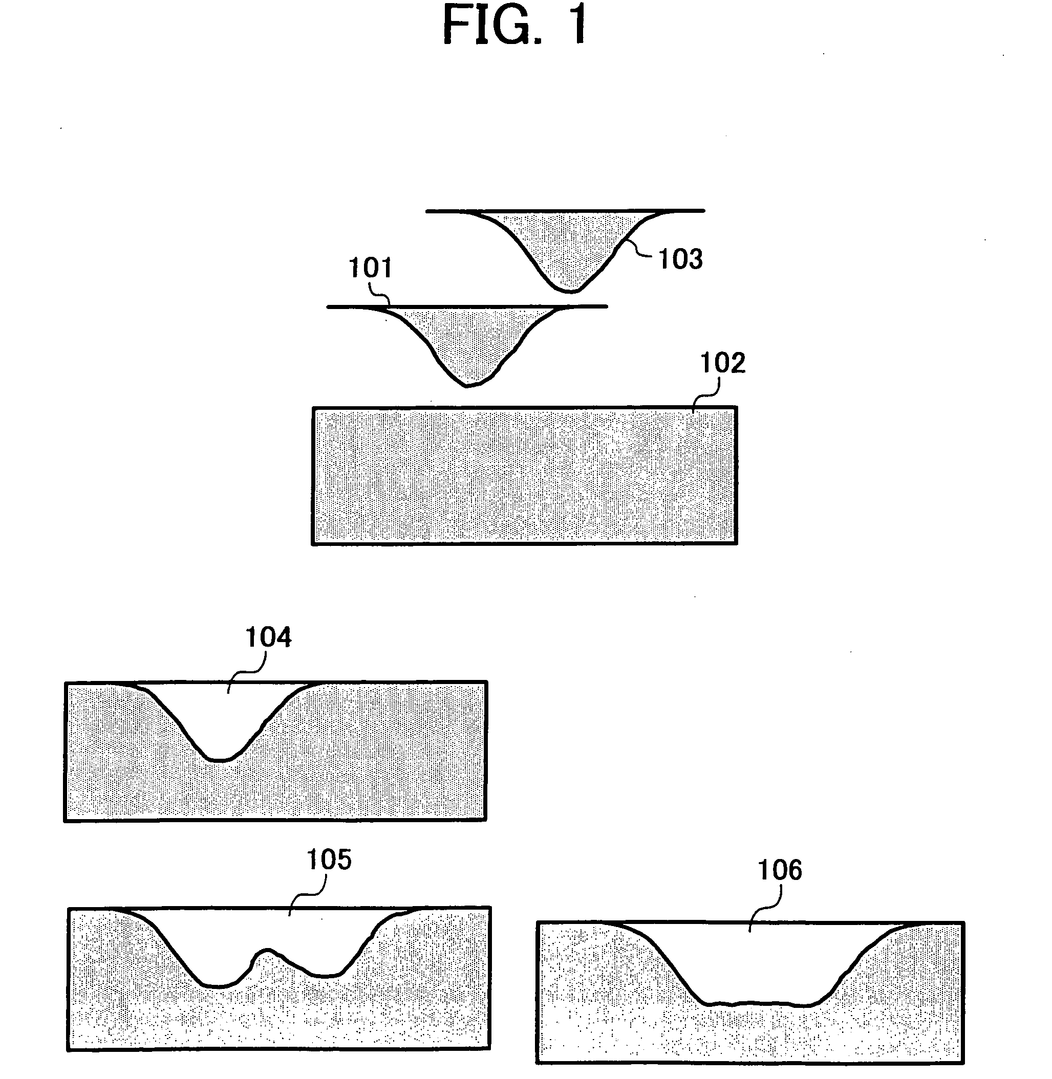
[0065] An example of the laser working method of the present invention will be explained with reference to FIG. 1.
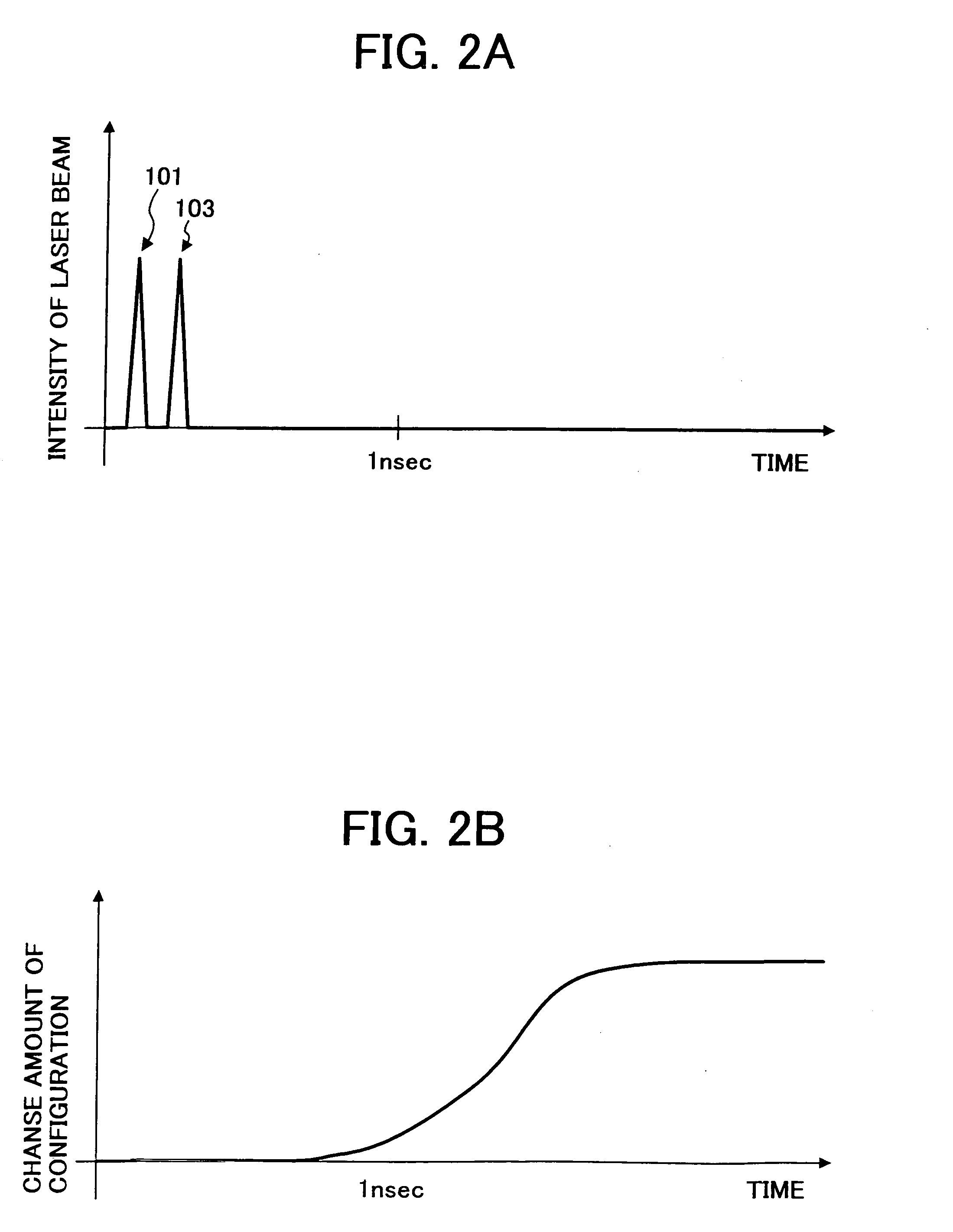
[0066] A first pulse laser beam 101 having a pulse time width of 100 fs is applied to an object 102 to be worked, and then a second pulse laser beam 103 having the same pulse time width of 100 fs is applied to the object. The worked shape with the first pulse laser beam is as indicated by 104. When the second pulse laser beam is applied after the termination of the working with the first pulse laser beam (that is, a few or several nanoseconds or more thereafter), the worked shape is as indicated by 105 in which a working efficiency decreases at an inclined surface formed with the first pulse laser beam. According to an example of the present invention, a worked shape is as indicated by 106 when the second pulse laser beam is applied 200 fs after the first pulse laser beam is applied. At that time, the intensity of the pulse laser beams applied to the working surface of ...
example 2
[0070] In Example 2, the intensity of at least one of the above plural pulse laser beams is adjusted with an ND filter or a polarization element. A device is preferably provided for adjusting the intensity of each of the laser beams so that their relative intensities may be freely varied. In the following, Example 2 will be explained with reference to FIG. 3.
[0071] First, a first pulse laser beam 301 having a pulse time width of 100 fs is applied to an object 302 to be worked. Then, a second pulse laser beam 304 of which intensity is adjusted to a half of that of the first pulse laser beam through the ND filter 303 is applied to the object 200 fs after the application of the first pulse laser beam. A worked shape having a three-dimensional step 305 can be obtained after the termination of working.
[0072] According to this Example, the three-dimensional worked shape can be realized by working, while the relative intensities of the plural pulse laser beams are varied.
example 3
[0073] In Example 3, a diffractive optical element is used for splitting a pulse laser beam. This will be explained with reference to FIG. 4.
[0074] A single pulse laser beam 401 is split into non-diffracted light beam 403 and plural primary diffracted light beams 404 by a diffractive optical element 402. At this time, the intensity ratio off the non-diffracted light beam 403 and plural primary diffracted light beams 404 is variable by appropriately designing the structure of the diffraction optical element 402. When a collimator lens 405 is installed downstream the beam splitting, the beams can be converted to plural parallel pulse beams. In this case, there is no time delay between the plural primary diffracted light beams 404, whereas there is a time delay between the non-diffracted light beam and plural primary diffracted light beams.
[0075] According to Example 3, the number and the intensity distribution of the split laser beams can be varied in various ways depending upon the...
PUM
| Property | Measurement | Unit |
|---|---|---|
| time | aaaaa | aaaaa |
| time | aaaaa | aaaaa |
| time width | aaaaa | aaaaa |
Abstract
Description
Claims
Application Information
 - R&D
- Intellectual Property
- Life Sciences
- Materials
- Tech Scout
- Unparalleled Data Quality
- Higher Quality Content
- 60% Fewer Hallucinations
Browse by: Latest US Patents, China's latest patents, Technical Efficacy Thesaurus, Application Domain, Technology Topic, Popular Technical Reports.
© 2025 PatSnap. All rights reserved.Legal|Privacy policy|Modern Slavery Act Transparency Statement|Sitemap|About US| Contact US: help@patsnap.com


