Bioabsorbable suture anchor system for use in small joints

a suture anchor and bioabsorbable technology, applied in the field of medical devices and procedures, can solve the problems of significantly less room for surgeons to perform the required manipulations at the surgical site, and the anchors currently available are too large for the insertion depth desired

Active Publication Date: 2005-01-27
DEPUY SYNTHES PROD INC
View PDF25 Cites 30 Cited by
  • Summary
  • Abstract
  • Description
  • Claims
  • Application Information

AI Technical Summary

Benefits of technology

[0009] The suture anchor also includes a suture channel that extends between the two opposed surfaces. The suture channel is formed in the elongate body to allow the passage of a suture strand therethrough, and it is preferably oriented to be transverse to the longitudinal axis of the anchor. The suture channel is flanked, or bordered on each side by an opening that is located on an opposed surface. To enable the suture strand to glide smoothly around the suture channel, the openings can be provided with rims that are flared or chamfered so as to avoid snagging or cutting the suture strand on a sharp edge of the opening as the suture strand passes back and forth within the suture channel. The center of each of the openings can be longitudinally offset with respect to the longitudinal axis of the elongate body. The offset channel enables a surgeon to toggle the suture anchor by pulling on an attached suture strand while the anchor is inside a bone cavity.

Problems solved by technology

One problem encountered in the less invasive, closed surgical procedures is that the surgeon has significantly less room to perform the required manipulations at the surgical site.
Where there is a need to reattach tissue to a relatively small bone in the patient's body, such as in the hand or the skull, the anchors currently available would be too large for the insertion depth desired.

Method used


Image

  • Bioabsorbable suture anchor system for use in small joints
  • Bioabsorbable suture anchor system for use in small joints
  • Bioabsorbable suture anchor system for use in small joints

Examples


Embodiment Construction

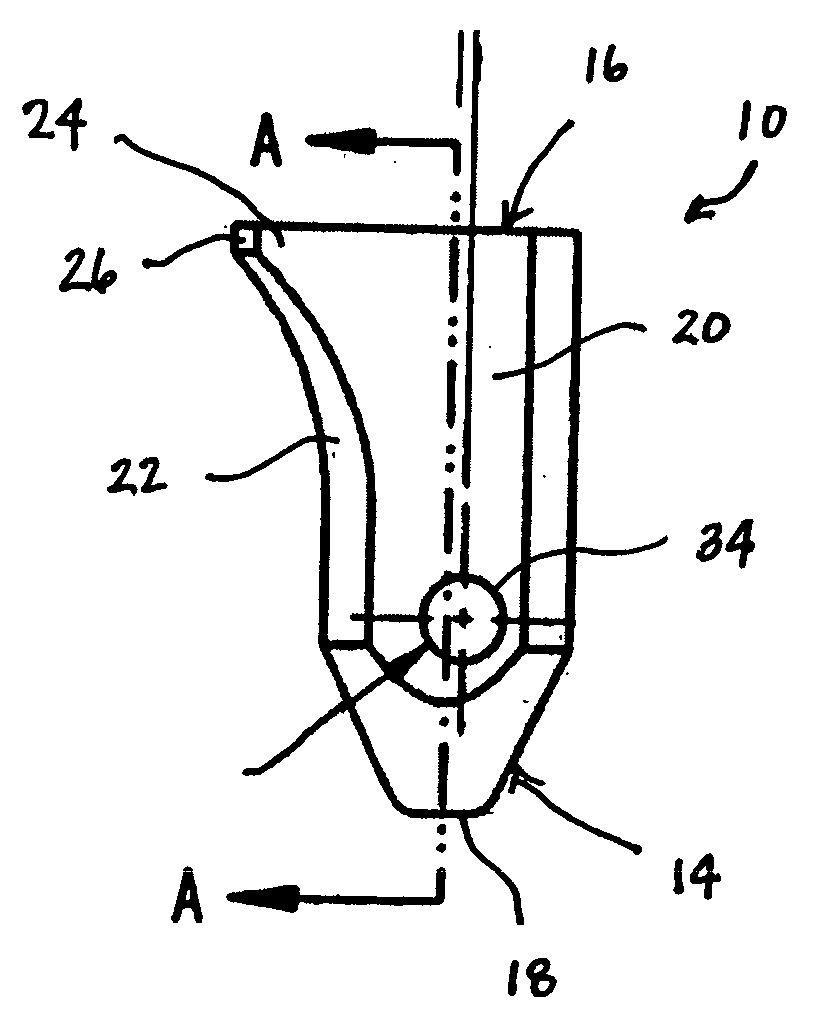
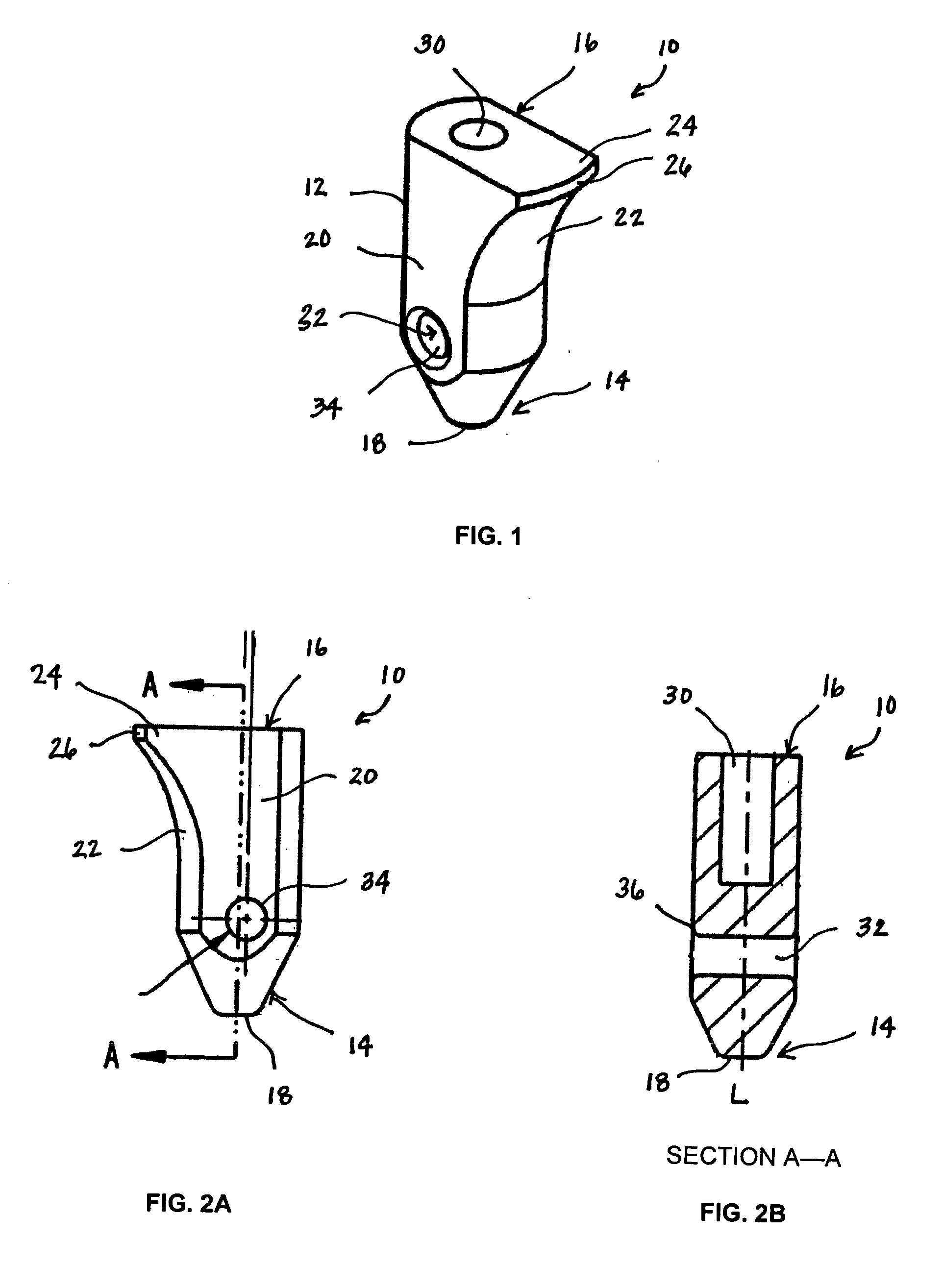
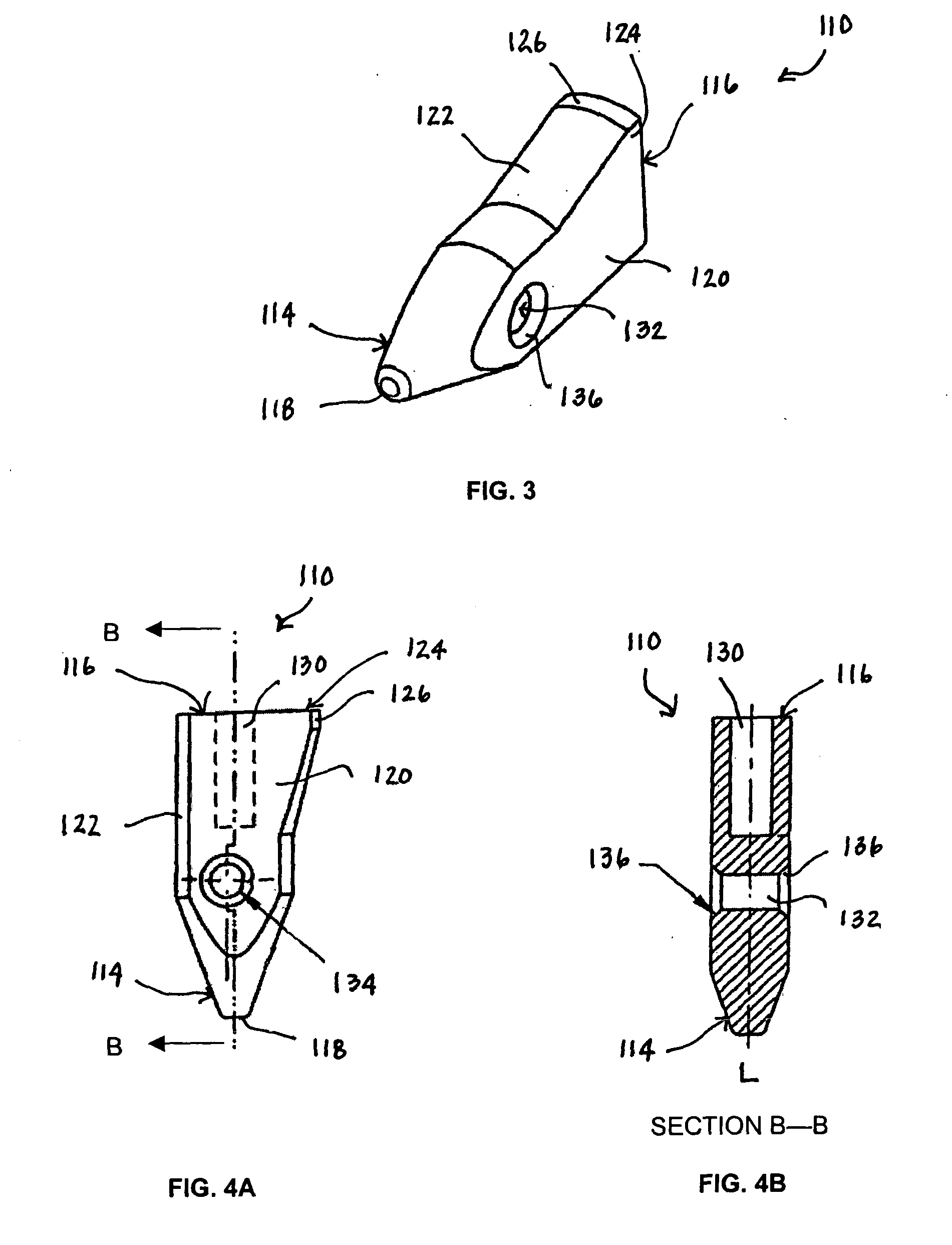
[0024] Referring to FIG. 1, an exemplary suture anchor 10 of the present invention is shown having an elongate body 12 extending between a first, leading end 14 and a second, trailing end 16 for defining a longitudinal axis L. The first, leading end 14 may be tapered as shown, and can extend into a blunt tip 18 having a continuous surface. Preferably, the blunt tip 18 has a smooth outer edge. Extending between the first and second ends 14, 16 are a pair of opposed surfaces 20 and a plurality of sidewalls 22 adjacent to and extending between the two opposed surfaces 20, which together define the elongate body 12. Near the second, trailing end 16 and extending from one of the plurality of sidewalls 22 is a flared portion 24. The flared portion 24 lends an asymmetric profile to the suture anchor 10 and facilitates the toggling action of the suture anchor 10 once inserted inside a bone cavity. The flared portion 24 also has a shape that is effective to penetrate into bone. For instance,...


PUM


Abstract

A bioabsorbable suture anchor for anchoring soft tissue to a bone is provided. The suture anchor is configured to toggle and anchor itself inside a bone cavity of a small joint. The anchor comprises an elongate body defined by a longitudinal axis, a first, leading end and a second, trailing end. The elongate body also has two opposed surfaces between the first and second ends, and a plurality of sidewalls extending between the two opposed surfaces. Extending from one of the sidewalls is a flared portion that is formed on the second end of the elongate body. The flared portion is adapted to engage and anchor into bone tissue upon toggling. A suture channel extends between the two opposed surfaces. The suture channel is formed in the elongate body for passage of a suture strand therethrough, such that pulling on an attached suture strand effects toggling of the anchor inside a bone cavity.

Description

CROSS-REFERENCE TO RELATED APPLICATIONS [0001] Not applicable. STATEMENT REGARDING FEDERALLY SPONSORED RESEARCH [0002] Not Applicable. FIELD OF THE INVENTION [0003] The invention relates generally to medical devices and procedures. Particularly, this invention relates to a bioabsorbable suture anchor system for attaching soft tissue to hard bone, and to methods for attaching soft tissue to hard bone. More particularly, the invention relates to a bioabsorbable suture anchor system configured for use in hand and craniofacial surgery. BACKGROUND OF THE INVENTION [0004] Soft tissues, such as ligaments, tendons and muscles, are attached to a large portion of the human skeleton. In particular, many ligaments and tendons are attached to the bones which form joints, such as shoulder and knee joints. A variety of injuries and conditions require attachment or reattachment of a soft tissue to bone. For example, when otherwise healthy tissue has been torn away from a bone, surgery is often requ...

Claims


Application Information

Patent Timeline
Patent Type & Authority Applications(United States)
IPC IPC(8): A61B17/56A61B17/04
CPCA61B17/0401A61B2017/0414A61B2017/0409
Inventor COOK, SHELBY L.LIZARDI, JOSE E.REESE, KARL S.SHEPARD, THOMAS A.
Owner DEPUY SYNTHES PROD INC
Why Eureka
Try Eureka