Method of rendering a mechanical heart valve non-thrombogenic with an electrical device

a technology of electrical device and mechanical heart valve, which is applied in the field of mechanical devices, can solve the problems of insufficient interference with the normal beating of the heart, and achieve the effect of reducing or eliminating blood clotting

Inactive Publication Date: 2005-01-27
JS VASCULAR
View PDF13 Cites 212 Cited by
  • Summary
  • Abstract
  • Description
  • Claims
  • Application Information

AI Technical Summary

Benefits of technology

[0016] In the most preferred embodiment, the power source is attached to a heart valve by wires capable of transferring an electrical current from the power source to the device. The power source is preferably placed in a subcutaneous pocket for easy access when and if battery changes are required. The power source can supply a sufficient current to the mechanical device to sufficiently charge the device (or part of the device) to reduce or eliminate blood clotting on one or more surfaces of the device. Preferably, the power supply creates a substantially constant appropriate and substantially unipolar electrically negative (or positive) charge to the device. The electrical charge applied to the device is sufficient to repel activated platelets and activated red blood cells from settling on the charged component of the device but will be insufficient to interfere with the heart's normal beating.
[0017] The new system is expected to provide one or more of the following benefits: First, energizing an implanted mechanical device may free that device from lifelong anticoagulation requirements. Second, disclosed herein is a new form of a power source that will be capable of supplying a preferably constant electrical charge to an implanted mechanical device. Third, the power source may have a primary and secondary (redundant) source of energy, such as a first battery and a second battery, wherein the second battery supplies power if the first battery fails. Fourth, only a relatively minor modification to an existing heart valve is required so as to connect it to a power source according to the invention. In a preferred method, paired leads are attached to the valve annulus and exit either a cardiac chamber or a blood vessel to connect to a power source according to the invention. The power source is preferably implanted in a subcutaneous position in the body and can be accessed for both telemetry and changing on an as necessary basis.

Problems solved by technology

The electrical charge applied to the device is sufficient to repel activated platelets and activated red blood cells from settling on the charged component of the device but will be insufficient to interfere with the heart's normal beating.
Third, the power source may have a primary and secondary (redundant) source of energy, such as a first battery and a second battery, wherein the second battery supplies power if the first battery fails.

Method used


Image

  • Method of rendering a mechanical heart valve non-thrombogenic with an electrical device
  • Method of rendering a mechanical heart valve non-thrombogenic with an electrical device

Examples


Embodiment Construction

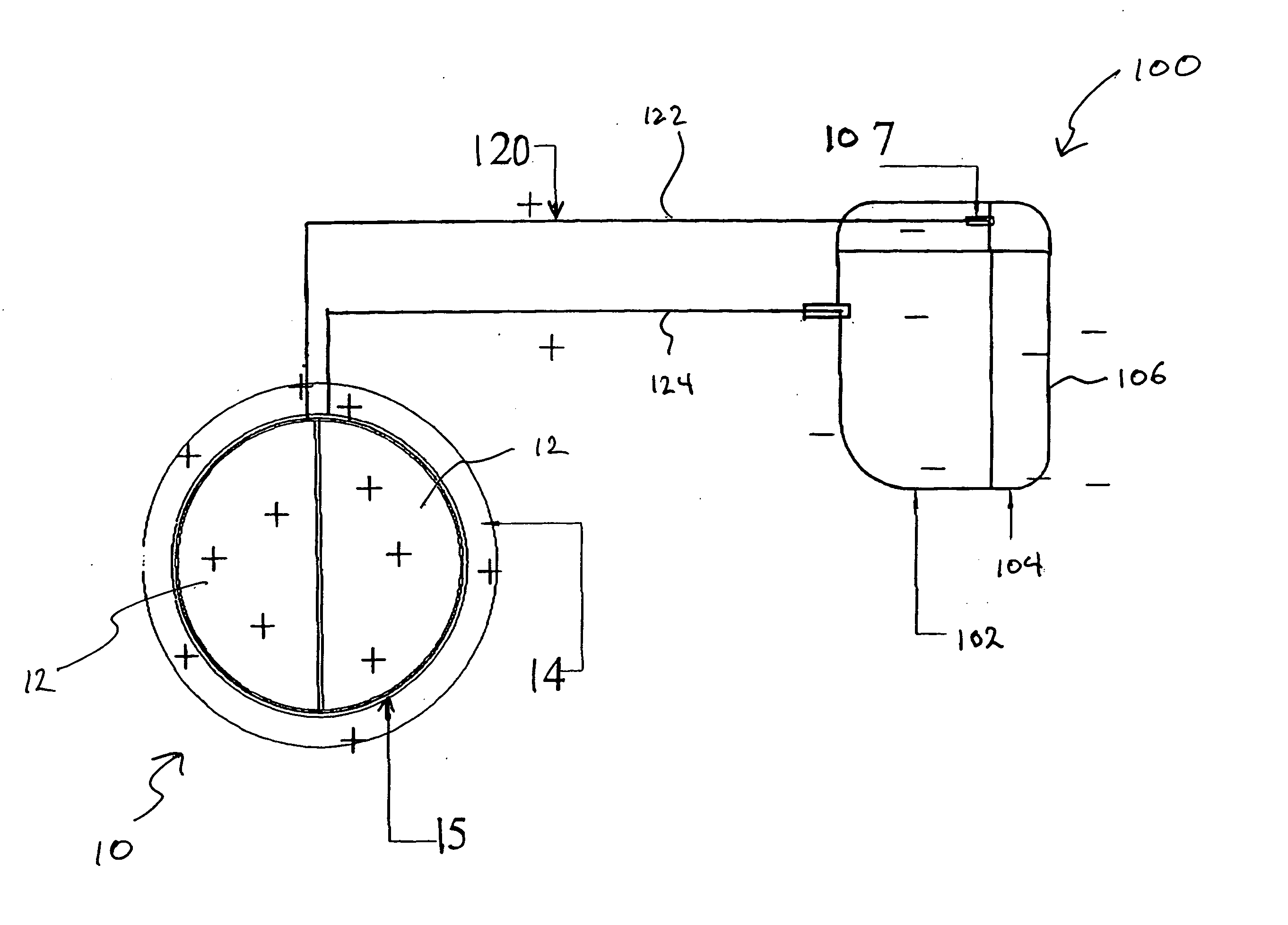
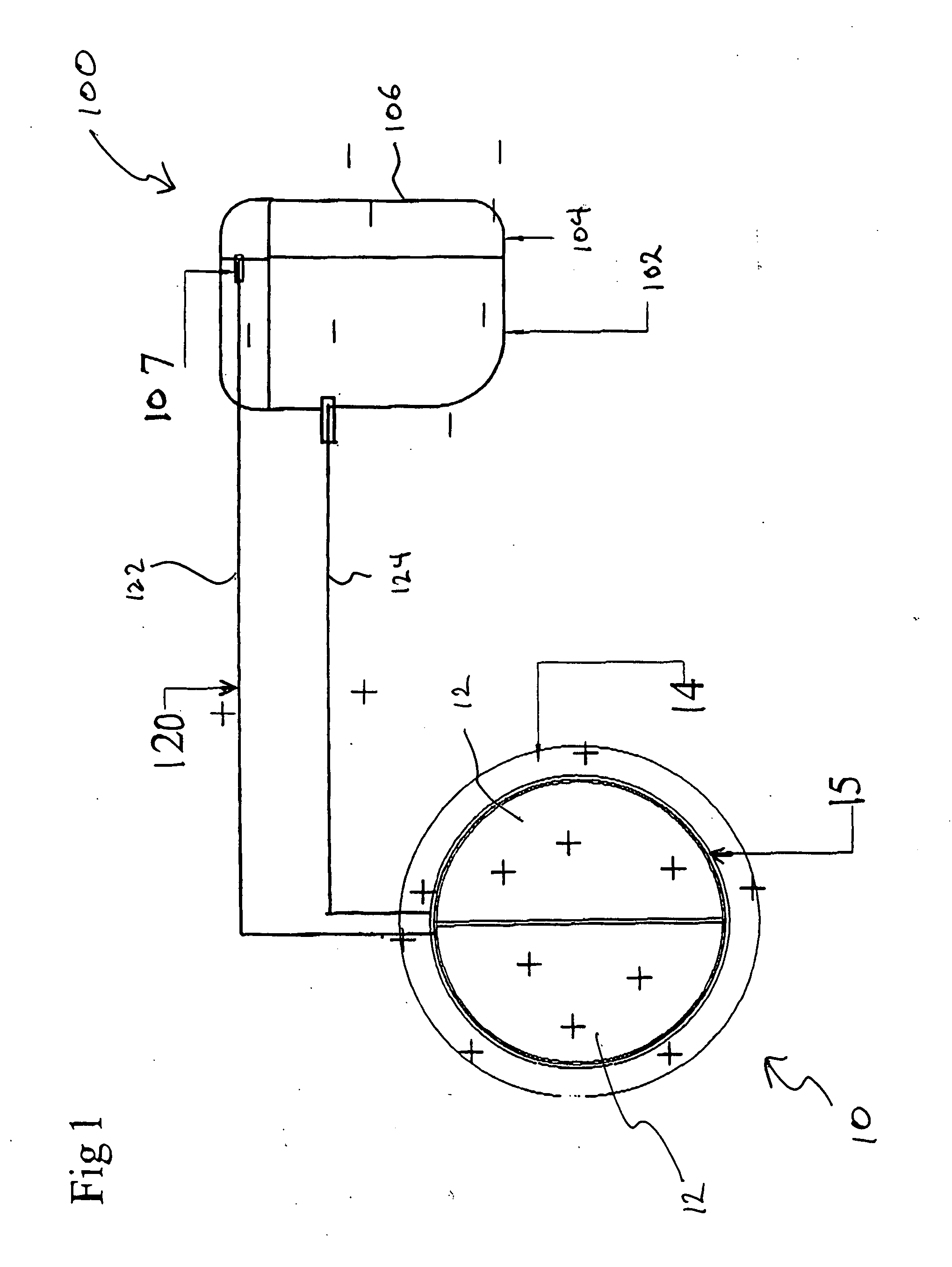
[0019] Turning now to the Drawing, where the purpose is to describe a preferred embodiment of the invention and not limit same, FIG. 1 is a schematic representation of a mechanical device and power supply according to the invention.

[0020] A device 10 according to the invention may be any mechanical device that is implanted into the body and that is susceptible to blood clotting on one or more of its surfaces to such a degree that interventional therapy is recommended to reduce or eliminate the clotting. Device 10 is preferably a heart valve, such as an aortic, tricuspid or mitral valve. Other examples of mechanical devices that may be used to practice the invention are pulmonary valves. In this embodiment, device 10 has a connective portion 11 (for receiving a connection to a power source or otherwise connecting device 10 to a power source), valve plates 12 and sewing ring 14. Device 10 can be made of any suitable materials that can be charged to prevent or alleviate blood clotting...


PUM

PropertyMeasurementUnit
voltageaaaaaaaaaa
voltageaaaaaaaaaa
currentaaaaaaaaaa

Abstract

A mechanical device for implantation into a patient's body is designed or modified to be electrically charged to prevent coagulation on the device, thereby extending the life of the device and alleviating the need for the patient to utilize anticoagulant therapy. The device may be a heart valve and is electrically charged by being connected to a power source. The power source is preferably a battery pack implanted in the body and is connected to the device by connector wires. The charge applied to the device may be negative or positive, as long as it helps to repel platelets and/or red blood cells from the device in order to help prevent coagulation on one or more surfaces of the device.

Description

RELATED APPLICATIONS [0001] This application claims priority to U.S. Provisional Application Ser. No. 60 / 484,038, filed Jun. 30, 2003, to John C. Opie.FIELD OF THE INVENTION [0002] The invention relates to medical devices permanently or semi-permanently implanted into the body and more particularly to a partially or totally non-thrombogenic mechanical device such as a heart valve. BACKGROUND OF THE INVENTION [0003] Currently, patients who have an implanted mechanical device, particularly a mechanical heart valve, must usually be anti-coagulated (by taking anti-coagulation medication) for life due to the fact that the heart valve acts as a local initiator for coagulation. Among the known mechanical heart valve designs are those disclosed in U.S. Pat. Nos. 6,645,244, 6,395,024, 6,699,283, 6,638,303 and 6,582,464, and U.S. patent application Ser. Nos. 10 / 133,859 and 10 / 717,817, the respective disclosures of which are incorporated herein by reference. [0004] Although not important for a...

Claims


Application Information

Patent Timeline
Patent Type & Authority Applications(United States)
IPC IPC(8): A61F2/00A61F2/02A61F2/24A61L27/50
CPCA61F2/02A61F2/2403A61L27/50A61F2210/0009A61F2002/30107
Inventor OPIE, JOHN C.
Owner JS VASCULAR
Why Eureka
Try Eureka