
Wavelet analysis of one or more time domain reflectometry (TDR) signals to determine one or more characteristics of one or more anomalies in a wire

a technology of time domain reflectometry and wavelet analysis, which is applied in the direction of resistance/reactance/impedence, spectral/fourier analysis, instruments, etc., can solve the problems of ineffective fts at analyzing tdr signals and inability to accurately represent tdr signals. to achieve the effect of accurately determining one or more characteristics and facilitating analysis of frequency conten

Active Publication Date: 2005-01-27
TEXAS INSTR INC
View PDF2 Cites 7 Cited by
  • Summary
  • Abstract
  • Description
  • Claims
  • Application Information

AI Technical Summary

Benefits of technology

[0004] According to the present invention, disadvantages and problems associated with analyzing one or more TDR signals may be reduced or eliminated.
[0006] Particular embodiments of the present invention may provide one or more technical advantages. Particular embodiments may facilitate analysis of frequency content of one or more TDR signals. Particular embodiments may be used to more accurately determine one or more characteristics of one or more anomalies in a wire. Certain embodiments may provide all, some, or none of these technical advantages. Certain embodiments may provide one or more other technical advantages, one or more of which may be readily apparent to those skilled in the art from the figures, descriptions, and claims herein.

Problems solved by technology

However, FTs tend to be ineffective at analyzing TDR signals.
A drawback of FTs is that, in an FT analysis of a function, the function is assumed to be periodic and to extend infinitely in a time domain.
As a result, FTs cannot accurately represent such TDR signals.

Method used


Image

  • Wavelet analysis of one or more time domain reflectometry (TDR) signals to determine one or more characteristics of one or more anomalies in a wire
  • Wavelet analysis of one or more time domain reflectometry (TDR) signals to determine one or more characteristics of one or more anomalies in a wire

Examples


Embodiment Construction

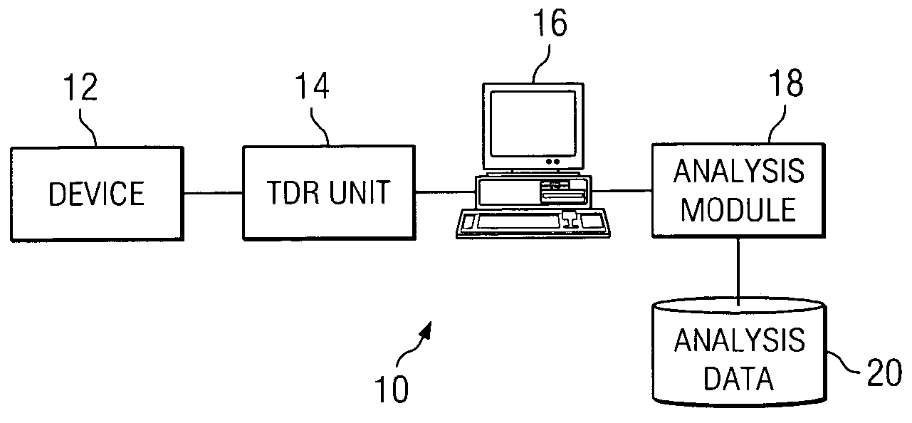
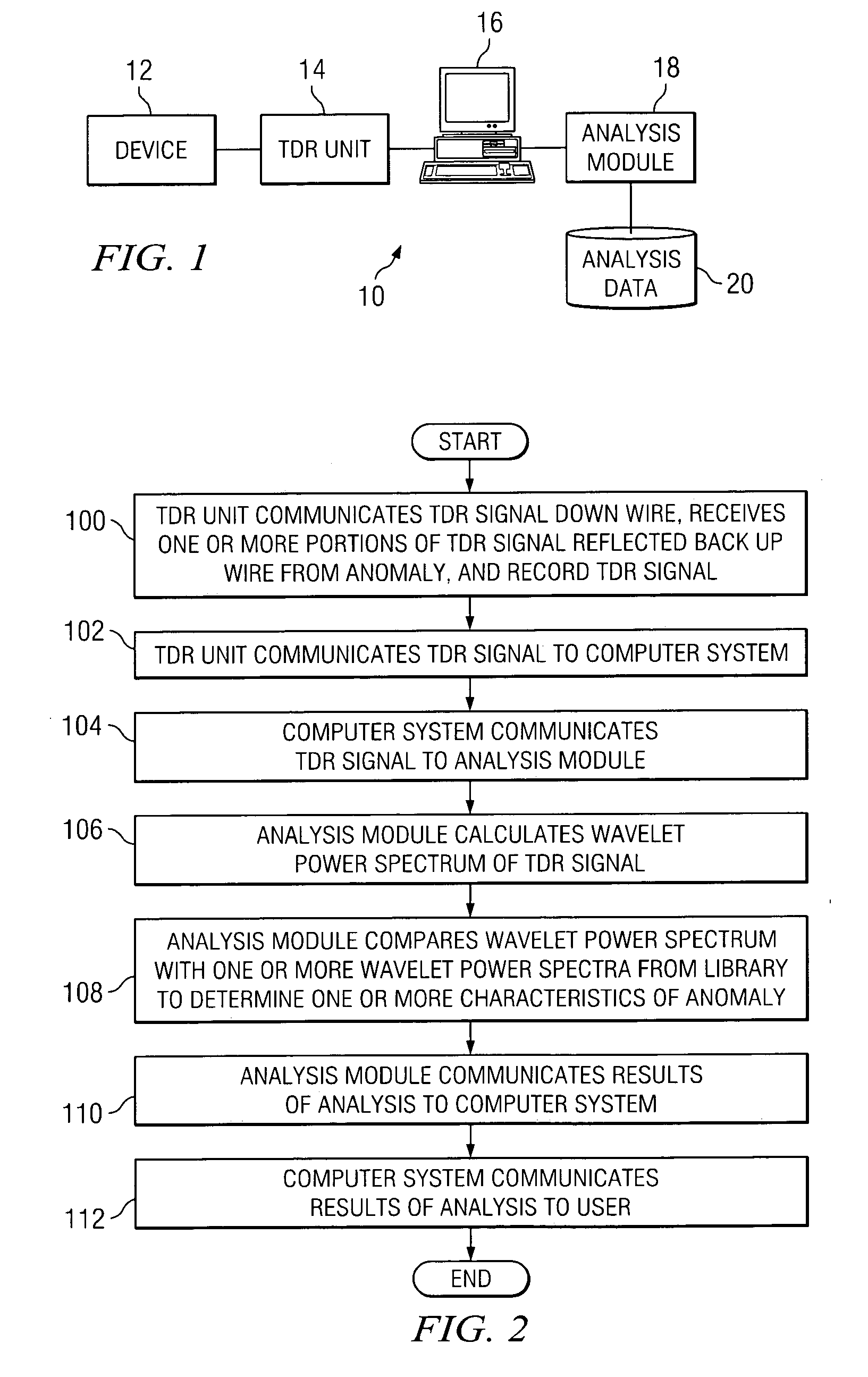
[0010]FIG. 1 illustrates an example system 10 for wavelet analysis of one or more TDR signals to determine one or more characteristics of one or more anomalies in a wire. System 10 includes a device 12, a TDR unit 14, a computer system 16, an analysis module 18, and analysis data 20. Device 12 is any suitable device including one or more wires (which may each include one or more conductive links coupling two or more components of device 12 to each other) for testing. As an example, in particular embodiments, device 12 is an integrated circuit (IC) package including one or more wires coupling input and output pins to solder bumps for electrically coupling the IC package to a die. As another example, in particular embodiments, device 12 is a die including one or more wires linking a land of the die (which may be coupled to a solder bump of an IC package) to one or more components of an IC in the die. Although particular devices 12 including particular wires are described, the present ...


PUM


Abstract

In one embodiment, a method for wavelet analysis of one or more time domain reflectometry (TDR) signals to determine one or more characteristics of one or more anomalies in a wire includes receiving a TDR signal that has reflected back up a wire from an anomaly in the wire, calculating a wavelet analysis result from a wavelet analysis of the TDR signal, accessing a library of one or more reference wavelet analysis results that each correspond to one or more known anomalies having one or more known characteristics, and comparing the wavelet analysis result with one or more reference wavelet analysis results. If the wavelet analysis result corresponds to one or more particular reference wavelet analysis results, it is indicated that the anomaly in the wire has one or more particular known characteristics of one or more particular known anomalies corresponding to the one or more particular reference wavelet analysis results. If the wavelet analysis result of the TDR signal does not correspond to one or more reference wavelet analysis results, it is indicated that the anomaly in the wire lacks one or more known characteristics of one or more known anomalies corresponding to one or more reference wavelet analysis results in the library.

Description

RELATED APPLICATION [0001] This Application claims the benefit, under 35 U.S.C. § 119(e), of U.S. Provisional Application No. 60 / 486,663, filed Jul. 11, 2003.TECHNICAL FIELD OF THE INVENTION [0002] This invention relates generally to TDR signal analysis and more particularly to wavelet analysis of one or more TDR signals to determine one or more characteristics of one or more anomalies in a wire. BACKGROUND [0003] Previous techniques for analyzing one or more TDR signals include analyzing the TDR signals using a Fourier Transform (FT). However, FTs tend to be ineffective at analyzing TDR signals. A drawback of FTs is that, in an FT analysis of a function, the function is assumed to be periodic and to extend infinitely in a time domain. In contrast, a TDR signal is typically a critically damped pulsed signal that, in a time domain, has a rapidly rising leading edge. As a result, FTs cannot accurately represent such TDR signals. SUMMARY OF THE INVENTION [0004] According to the present...

Claims


Application Information

Patent Timeline
IPC IPC(8): G01R13/00G01R27/04
CPCG01R27/04G01R31/2853G01R31/66
Inventor WILLS, KENDALL S.RAMANUJACHAR, KARTIKDOCKINS, MICHAEL D.
Owner TEXAS INSTR INC
Learn More