Software verification method for control units and verification system

a software verification and control unit technology, applied in computer control, program control, instruments, etc., can solve the problems of established test technologies, difficult and complex verification of software functions, and the inability to test in vehicles, so as to reduce the risk of development, reduce the risk of failure, and increase the quality of softwar

Inactive Publication Date: 2005-01-27
ROBERT BOSCH GMBH
View PDF9 Cites 26 Cited by
  • Summary
  • Abstract
  • Description
  • Claims
  • Application Information

AI Technical Summary

Benefits of technology

[0015] Therefore, besides the software verification, a multistage function development process, using which the software quality may be increased and the development risk may be minimized in each phase, also results, which provides a high potential for cost savings.

Problems solved by technology

The increasing complexity of the control unit functions and / or of the individual automobile control units (electronic control units, ECU), but also the increasing networking and interaction of the control units and control unit functions in the vehicle composite system, as well as increased quality and safety requirements, make the verification of the software functions difficult and very complex.
Precisely in the field of automobiles, this is frequently only possible in the vehicle and is accordingly costly.
Since only very limited memory and run-time resources are available in standard control units for reasons of cost, the use of established test technologies, such as for code coverage analysis during the software release, is frequently not possible or is associated with increased costs.
However, if an additional code coverage memory and the corresponding computing time are not available, which is typical in a standard control unit, the method according to German Published Patent Application No. 199 59 247 is therefore not feasible.
This situation leads to a goal conflict with the high real-time capability and reliability of the systems which is simultaneously required.

Method used


Image

  • Software verification method for control units and verification system
  • Software verification method for control units and verification system
  • Software verification method for control units and verification system

Examples


Embodiment Construction

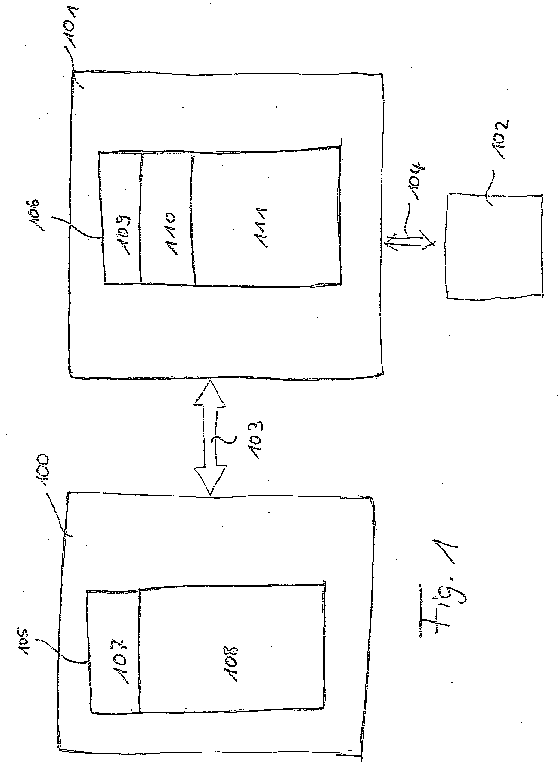
[0019] For this purpose, FIG. 1 shows a standard control unit 100, the ECU target, and experimental control unit 101, the experimental target. Both control units 100 and 101 are connected via a communication link 103. Depending on the application, this communication link may be unidirectional or bidirectional, serial or parallel, etc. Furthermore, a visualization and / or analysis means 102, which is also referred to in the following as a GUI or graphical user interface, is connected to experimental target 101. The link itself, whether parallel or serial and unidirectional or bidirectional, is identified with 104 here. This visualization means 102 may, as already noted, also include an analysis capability, i.e., a computing unit and / or a memory unit, this GUI also being able to be integrated in the experimental target.

[0020] The ECU software architecture and the software architecture of the experimental target are symbolically shown using blocks 105 and 106. The architecture of the s...


PUM


Abstract

A method and system for the verification of software functions for a control unit, using a simulation model to simulate the software functions and the control unit, the software code for the software functions being generated automatically from the identical simulation model, firstly for a first experimental control unit and secondly for a second standard control unit, identical input variables for the software functions being used on both control units and the output variables of both control units resulting therefrom being detected synchronized in time, i.e., simultaneously, the software functions being verified through comparison of the output variables of both control units.

Description

FIELD OF THE INVENTION [0001] The present invention relates to a method and a system for the verification of software functions for a control unit according to the independent claims. Furthermore, the present invention relates to a computer program, including program code elements for executing a method for software verification. BACKGROUND INFORMATION [0002] The increasing complexity of the control unit functions and / or of the individual automobile control units (electronic control units, ECU), but also the increasing networking and interaction of the control units and control unit functions in the vehicle composite system, as well as increased quality and safety requirements, make the verification of the software functions difficult and very complex. This also applies to the networking of control units and modules in other technical fields, such as machine tool manufacture, automation, etc. Currently, the software release for the individual systems is performed through systematic ...

Claims


Application Information

Patent Timeline
Patent Type & Authority Applications(United States)
IPC IPC(8): G06F11/28G05B19/042G05B23/02G06F9/44G06F11/07G06F11/277G06F11/36G06F17/50
CPCG05B19/0428G05B2219/23188G05B2219/24006G05B2219/24034G05B2219/24038Y02T10/82G06F11/0736G06F11/0739G06F11/0751G06F11/3684G06F11/3688G05B2219/24061
Inventor WOLFF, HANS-JOERGZURAWKA, THOMASSCHAEUFFELE, JOERG
Owner ROBERT BOSCH GMBH
Why Eureka
Try Eureka