Flame-resistant cable

a flame-resistant cable and filler technology, applied in the direction of plastic/resin/waxes insulators, organic insulators, conductors, etc., can solve the problems of reducing the insulating performance of the cable, the risk of fire propagation is particularly high, and it is not possible to incorporate flame-resistant fillers into the insulating layer of the medium-voltage or high-voltage cable. to achieve the effect of minimizing the secondary effect of fire-proofing

Inactive Publication Date: 2005-02-03
SILEC CABLE
View PDF11 Cites 57 Cited by
  • Summary
  • Abstract
  • Description
  • Claims
  • Application Information

AI Technical Summary

Benefits of technology

[0011] An object of the invention is to make an electric cable flame resistant in which the insulating layer of the cable is not flame resistant, while minimizing the secondary effects of such fireproofing. BRIEF SUMMARY OF THE INVENTION
[0012] In order to achieve this object, the invention provides a flame-resistant electric cable comprising at least one central conductor surrounded by an insulating layer itself surrounded by an outer sheath comprising an inner layer of flame-resistant synthetic material that conserves mechanical stability when it is subjected to a source of heat leading to softening, and an outer layer of a flame-resistant synthetic material in contact with the inner layer and decomposing into a thermally insulating layer when it is subjected to a source of heat leading to its decomposition.
[0013] Thus, it has been found, surprisingly, that compared with a uniform sheath of determined thickness, the sheath structure of the invention makes it possible for the same total thickness of sheath to obtain significantly reinforced protection against fire.

Problems solved by technology

Unfortunately, incorporating flame-resistant fillers in the insulation of cables diminishes their insulating characteristics, which means that it is not possible to envisage incorporating flame-resistant fillers into the insulating layer of a medium-voltage or a high-voltage cable.
The insulating layer of such a cable thus constitutes a potential source of fire propagation.
The risk of fire propagating is particularly high for nigh-voltage cables which generally comprise, between the conductor and the insulating layer, and also between the insulation and a metal shield of the cable, layers that serve to reduce electrical stresses, which layers essentially comprise an olefin polymer made conductive by a large quantity of carbon black so that, together with the insulation, they constitute a dangerous fuel in the event of a fire.
Nevertheless, specifically because of this mechanical stability, cross-linked materials are poor thermal insulators, such that prolonged exposure of the cable to a source of heat rapidly leads to the underlying insulating layer melting, and its weight then runs the risk of causing the outer sheath to burst, thereby releasing a highly combustible liquid from the cable and leading to instantaneous propagation of the fire.
Nevertheless, the initial expansion of the thermoplastic layer considerably reduces its mechanical stability and there therefore exists a significant risk of the sheath breaking up, with fragments of it dropping away so that the flames can then come directly into contact with the underlying layers of the cable.
Nevertheless, that raises problems of expense not only during manufacture of the cable but also when laying it because of the size and the weight of a cable with a thick sheath.
Such a structure nevertheless leads to an increase in the cost of manufacturing the cable.
In addition, in order to achieve effective holding, the holding sheet of fiberglass must itself be of sufficient thickness, thereby increasing the stiffness of the cable and thus making it more difficult to handle.

Method used


Image

  • Flame-resistant cable
  • Flame-resistant cable

Examples


Embodiment Construction

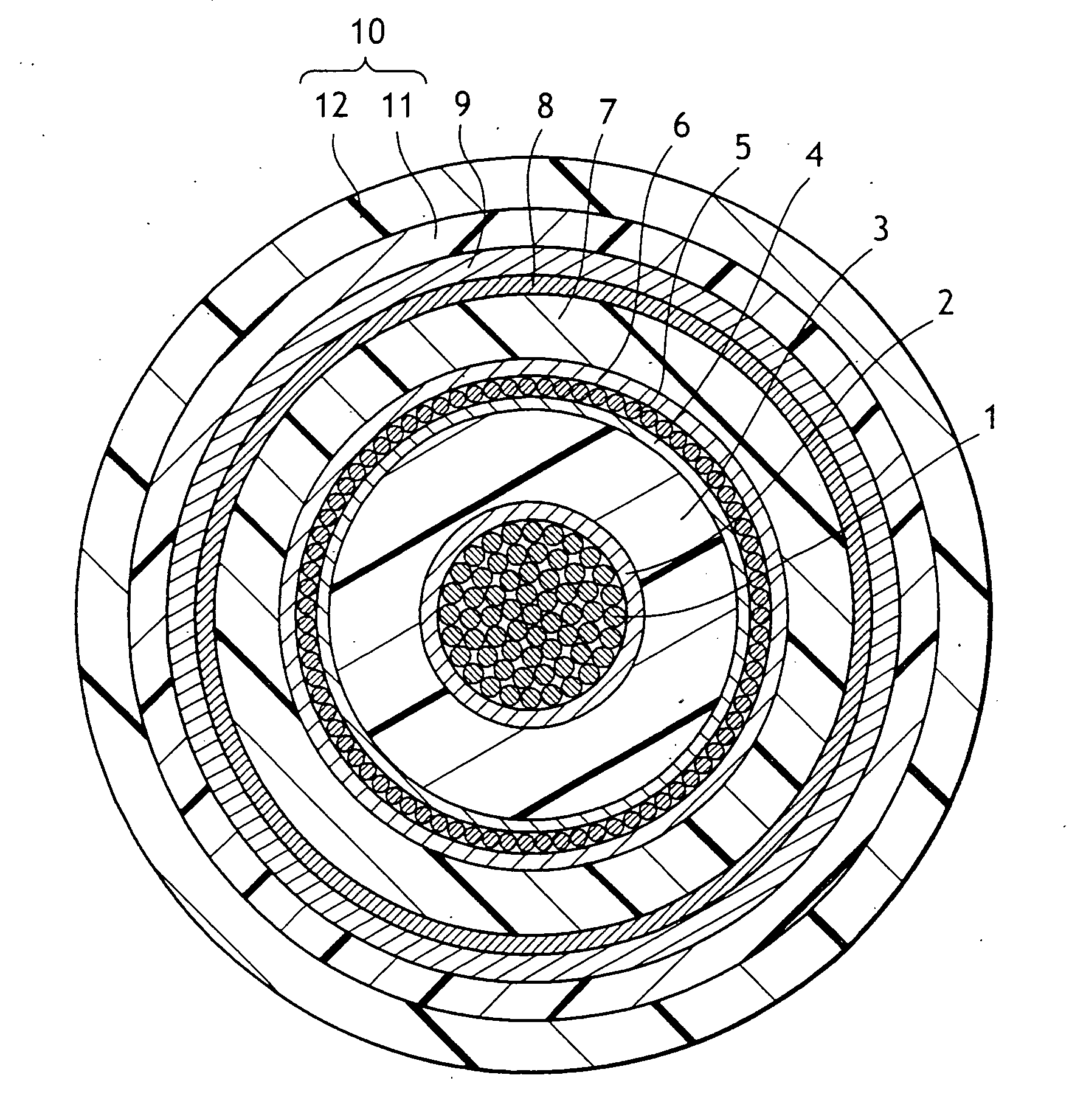
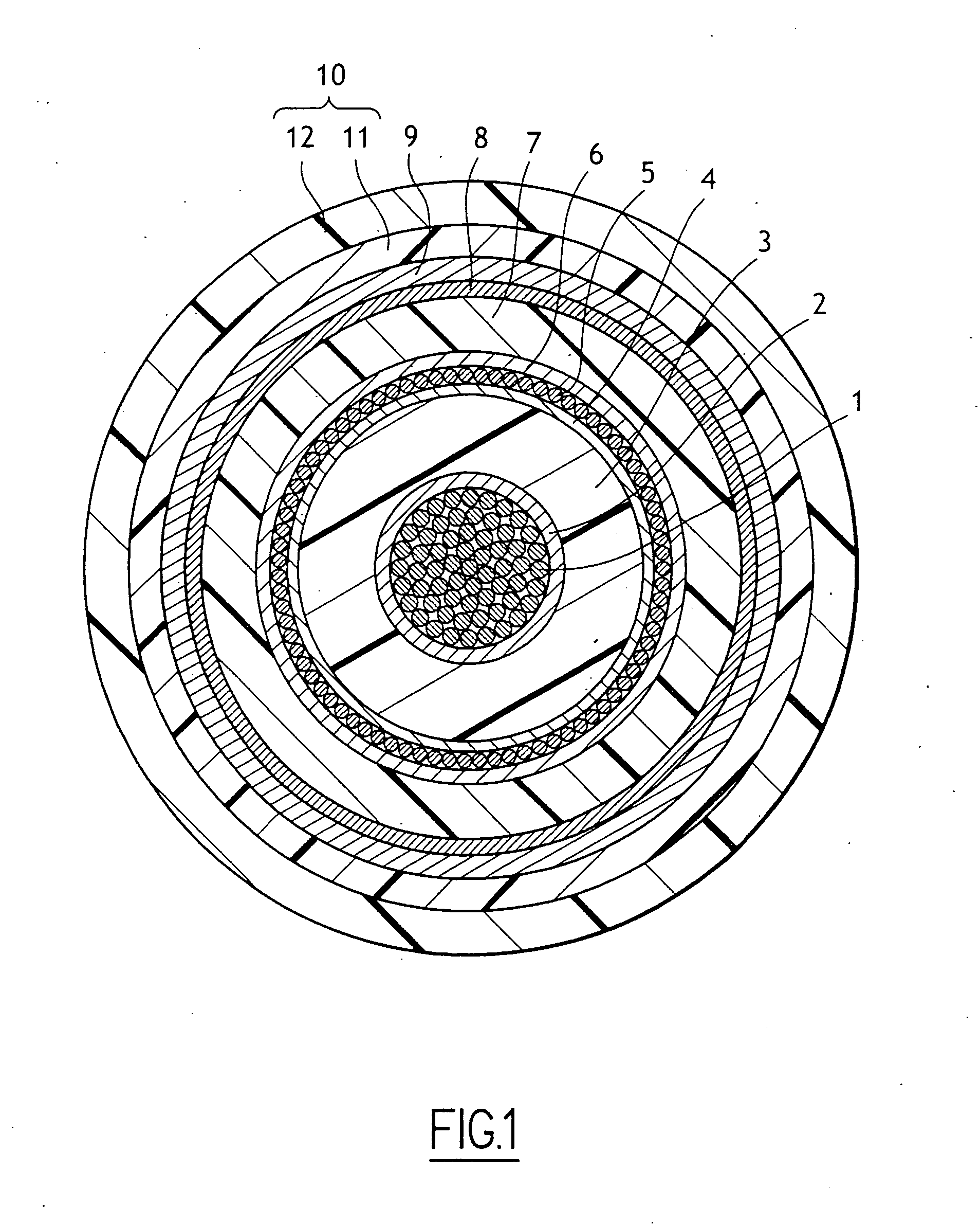
[0016] With reference to FIG. 1, the cable of the invention is shown with the thicknesses of its layers deliberately out of proportion compared with reality in order to facilitate understanding. The cable shown comprises in conventional manner a central conductor 1 made up of copper wires that are twisted together. The central conductor is surrounded in succession by a layer 2 for reducing electrical stress, an insulating layer 3, a second layer 4 for reducing electrical stress, a second electrical conductor 5 constituted by a sheet of copper wires wound helically, a third layer 6 for reducing electrical stress, a second insulating layer 7, a fourth layer 8 for reducing electrical stress, a metal shield 9 constituted by a helically-wound copper tape, and an outer sheath 10 in contact with the metal shield 9.

[0017] In accordance with the invention, the outer sheath 10 comprises an inner layer 11 of a flame-resistant synthetic material that conserves mechanical stability when it is s...


PUM

PropertyMeasurementUnit
Fractionaaaaaaaaaa
Thicknessaaaaaaaaaa
Heataaaaaaaaaa

Abstract

The flame-resistant electric cable comprising at least one central conductor surrounded by an insulating layer, itself surrounded by an outer sheath comprising an inner layer of flame-resistant synthetic material that conserves mechanical stability when it is subjected to a source of heat leading to softening, and an outer layer of a flame-resistant synthetic material in contact with the inner layer and decomposing into a thermally insulating layer when it is subjected to a source of heat leading to its decomposition.

Description

[0001] The present invention relates to a flame-resistant cable. BACKGROUND OF THE INVENTION [0002] For many years it has been known that in order to avoid risks of fire propagating, in particular in public places, it is desirable to make electric cables flame resistant. [0003] For low-voltage cables which are generally very simple in structure comprising one or more conductors each surrounded by an insulating layer and covered an outer sheath, the cable is generally made flame resistant by causing the insulating layer and in the outer sheath to incorporate flame-resistant fillers such as aluminum hydroxide or magnesium hydroxide which decompose at high temperatures to produce water. [0004] Given the increasing power of electricity distribution networks due to the increasing amount of electrical equipment running on electricity in public places, it is now necessary to bring in electricity at medium voltage or even at high voltage into town centers before transforming it to low volta...

Claims


Application Information

Patent Timeline
IPC IPC(8): B32B1/08B32B27/08B32B27/20H01B3/44
CPCB32B1/08B32B27/08H01B3/447H01B3/441B32B27/20
Inventor MAMMERI, MOHAMMEDPETRUS, RAYMONDPOISSON, BERNARDRAOULT, GWENAELLE
Owner SILEC CABLE
Why Eureka
Try Eureka