Tamper evident vial cap and integrity assurance method

a technology of integrity assurance and vials, applied in the field of tamper evident vials and caps therefor, can solve problems such as tamper evident, and achieve the effect of limiting upward movement of the loop

Active Publication Date: 2005-02-03
PII EVERGREEN
View PDF9 Cites 46 Cited by
  • Summary
  • Abstract
  • Description
  • Claims
  • Application Information

AI Technical Summary

Benefits of technology

[0006] In a particular embodiment, the vial is provided with a screw thread top and the tamper evident cap can be screwed onto the vial. A loop formed to encircle the vial is connected by a tether to the cap and slipped onto the vial. At least one restraining rib on the vial is spaced below the screw thread top and is sized to permit the loop to be forced upwardly thereover to be restrained from downward movement. In addition, at a limiting circumferential flange on the vial is spaced below the screw thread and above the loop restraining rib sufficient to accommodate the loop, and is sized to limit upward movement of the loop.

Problems solved by technology

The integrity of the device depends on a plastic, easily broken, thus tamper evident, tape that is sealed across the cap and vial.
There are a number of deficiencies in such a system, one of which being that once the tape is broken, there is no longer any tamper evident mechanism, and the chain of custody must be maintained by other means, for example by affidavits and / or testimony.
Another deficiency is that if care is taken by someone dedicated to the task, such a tape seal can be removed to unscrew the cap, and then the cap and tape can be replaced without the tampering being evident.

Method used


Image

  • Tamper evident vial cap and integrity assurance method
  • Tamper evident vial cap and integrity assurance method
  • Tamper evident vial cap and integrity assurance method

Examples


Embodiment Construction

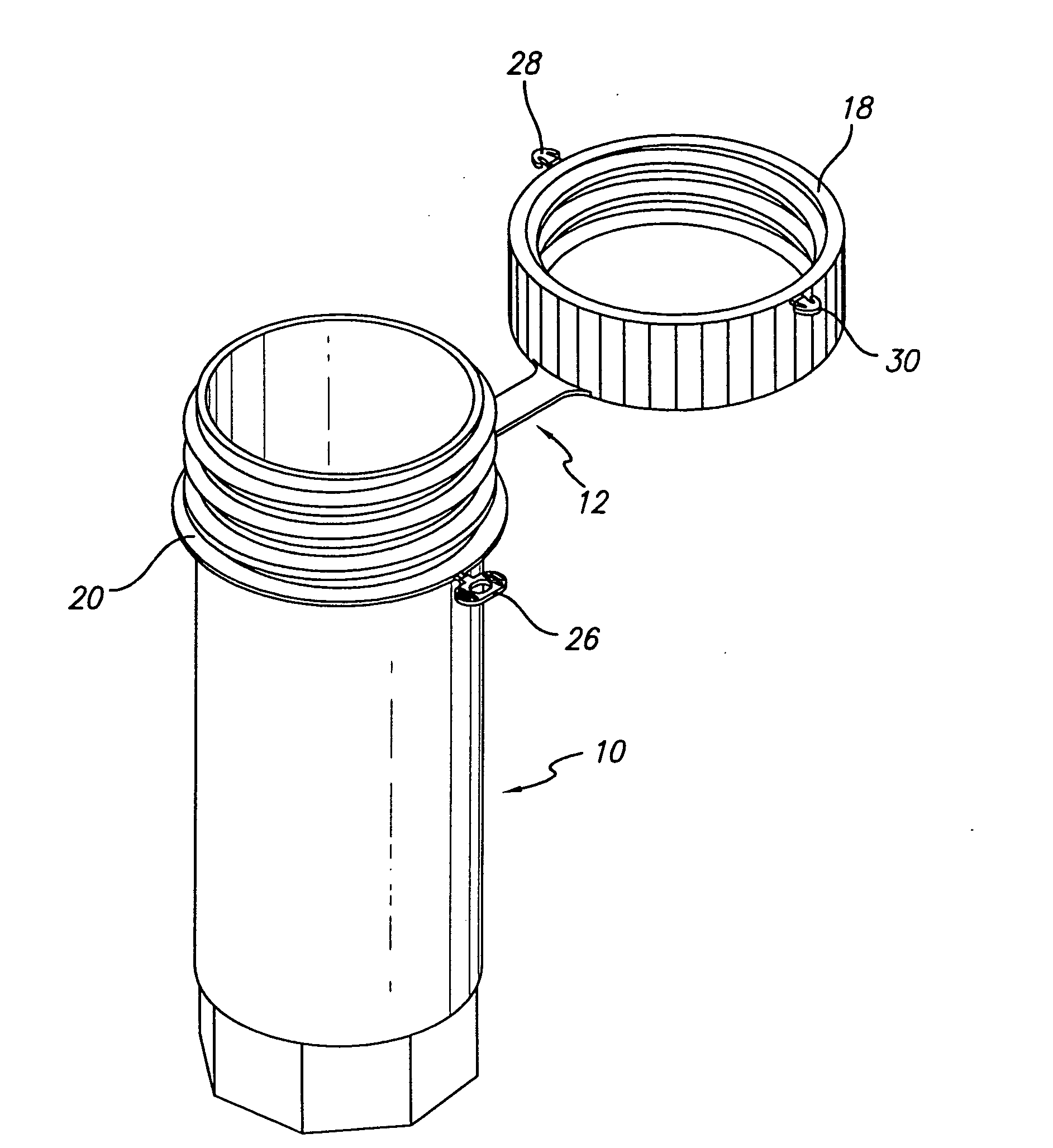
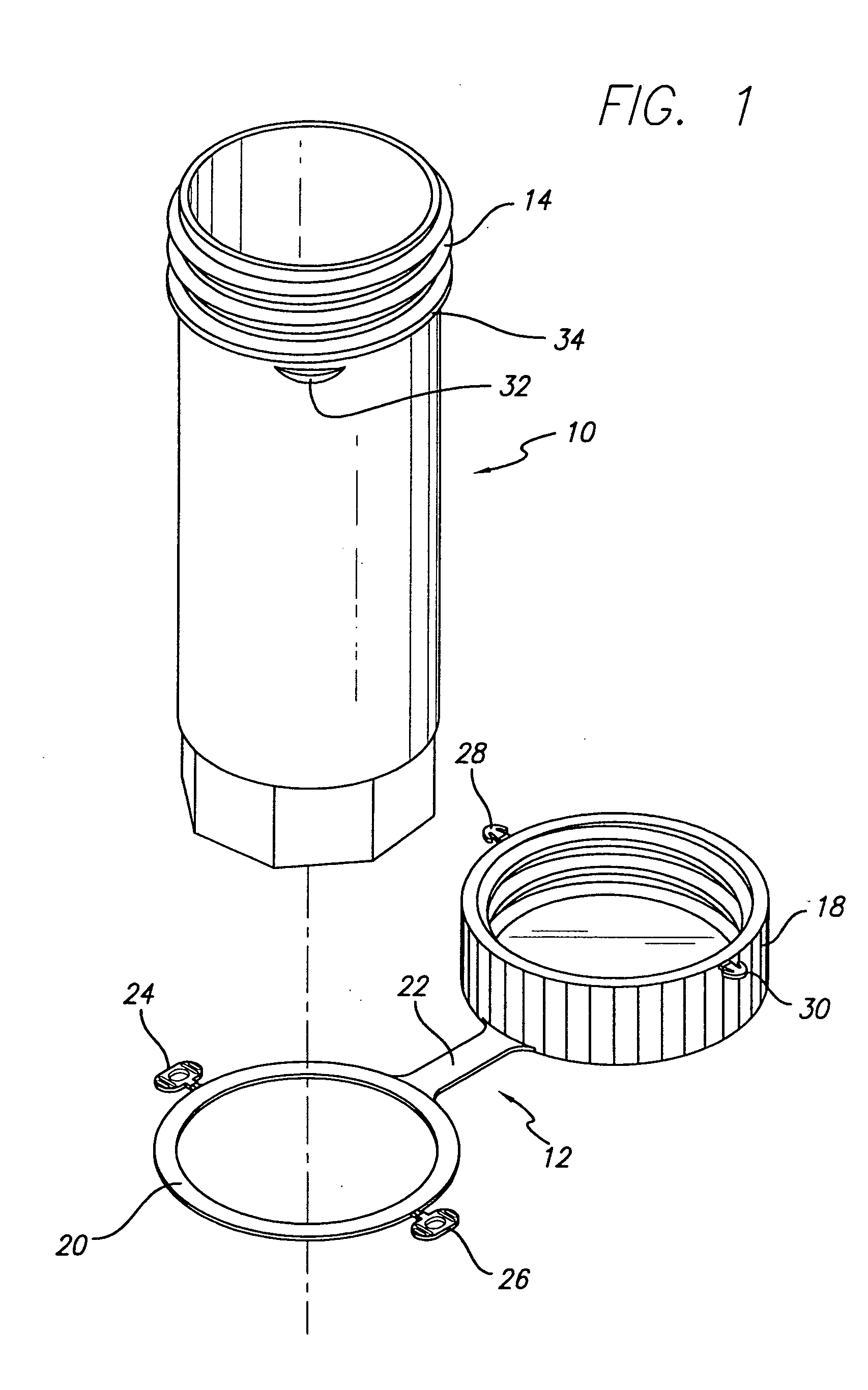
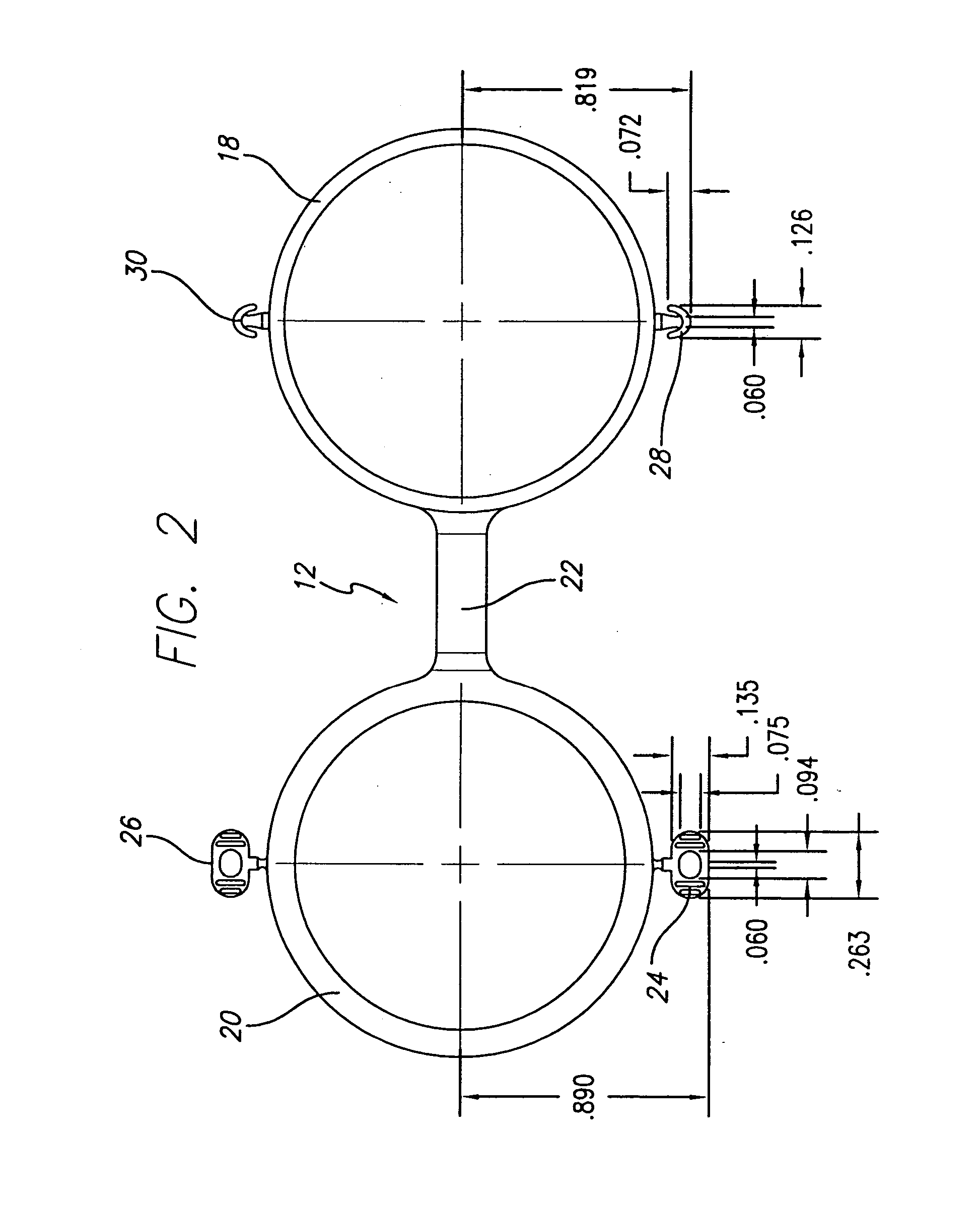
[0020] Referring to FIGS. 1-4, a combination of vial 10 and tamper evident cap assembly 12 are provided. Except as described below, the vial 10 has generally a known construction for a specimen vial formed with a screw thread top 14. The vial 10 can be provided with an octagon—shaped bottom 16 to fit into an automatic analyzer, but that is not itself part of the invention. The cap assembly 12 consists of a heavy-duty screw cap 18 to which a retaining loop is connected by a tether 22. Except for the latching components described below, the cap—tethered loop assembly 12 also has generally a known construction.

[0021] In accordance with the invention, the cap assembly and vial are each modified from the prior art to provide locking latches that enable the combination to be tamper evident and to provide a unique method of assuring the integrity and chain of custody of specimen collection. In particular, the retaining loop 20 is provided with a pair of hasps 24 and 26 and the cap 18 is p...


PUM


Abstract

A tamper evident cap assembly, more particularly a combination of vial and cap assembly, assures the integrity of a specimen and of the specimen collection process. The screw cap is locked to the screw threads of a vial, when the vial is empty, with one of two latches that are integral to the cap assembly and can lock the cap to the vial. The lock is broken in the presence of the specimen donor or in the presence of a witness who can testify as to chain of custody, a specimen is placed in the vial, following which the cap is locked to the vial with the other of the two latches, which is broken when received by a testing laboratory. A loop formed to encircle the vial is connected by a tether to the cap and slipped onto the vial. At least one restraining rib on the vial is spaced below the screw thread top and is sized to permit the loop to be forced upwardly thereover to be restrained from downward movement. In addition, a limiting flange on the vial is spaced below the screw thread and above the loop restraining rib sufficient to accommodate the loop, and is sized to limit upward movement of the loop. In a specific embodiment, latch staples extend from the cap which can be inserted into, and irreversibly lock with, respective hasps extending from the loop.

Description

FIELD OF THE INVENTION [0001] The invention relates to tamper evident vials and caps therefor, and to a method for assuring the integrity of specimen collection. BACKGROUND OF THE INVENTION [0002] Employers, government agencies, sports teams and other organizations have become increasingly involved in diagnostic testing to maintain safety in the workplace and to assure compliance with laws, rules and regulations. The presence of a predetermined analyte (e.g. drugs and / or disease) is determined by collecting biological fluids, i.e., urine, blood, sputum, pleural, cavity and peritoneal cavity fluids, for analysis. It is often vital in conducting such tests to maintain the integrity of the collected biological fluid specimens by minimizing or eliminating any potential for specimen contamination and / or by preserving the chain of custody. [0003] There are many and varied known devices for collecting specimens. A particular device consists of a vial fitted with a heavy-duty screw cap atta...

Claims


Application Information

Patent Timeline
Patent Type & Authority Applications(United States)
IPC IPC(8): B65D55/16
CPCB65D2101/0023B65D55/16B65D2401/15
Inventor WONG, JOHNSON N.S.
Owner PII EVERGREEN
Why Eureka
Try Eureka