
Method and apparatus for cutting off glass panes from a continuously produced glass sheet

Inactive Publication Date: 2005-02-03
SCHOTT AG
View PDF6 Cites 35 Cited by
  • Summary
  • Abstract
  • Description
  • Claims
  • Application Information

AI Technical Summary

Benefits of technology

[0010] It is an object of the present invention to provide a method and apparatus for cutting off glass panes from a continuously produced glass sheet, which provides a higher yield, particularly of good quality glass panes without glass faults.
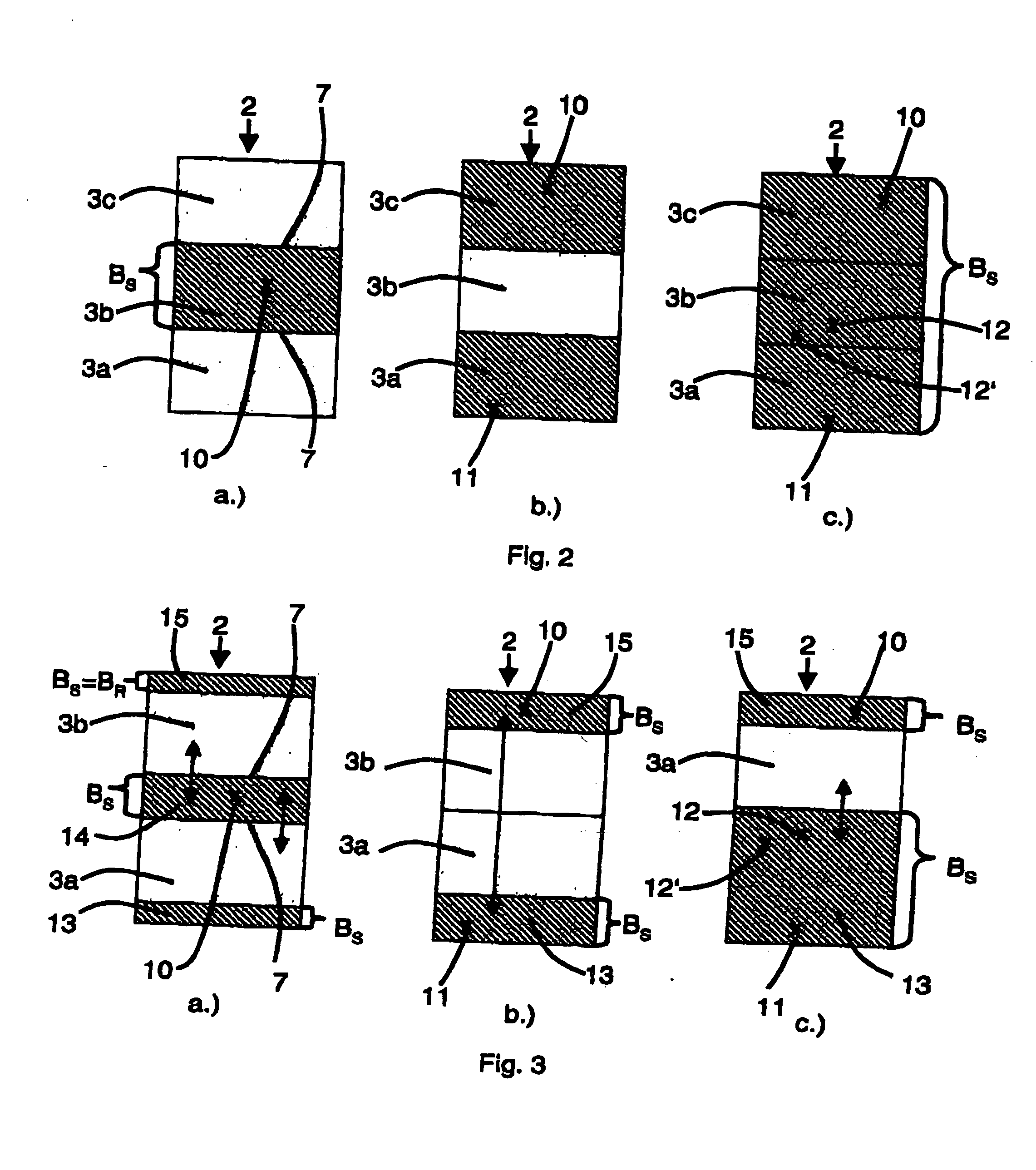
[0011] This object is attained with a method, in which the cutting lines for the glass panes to be cut off within each crosscut piece are placed in the fault-containing glass sheet regions to be discarded, so that the widths of the glass sheet regions to be discarded are minimized while providing a largest possible number of usable glass panes.
[0012] The invention is founded on the understanding that the yield of usable glass panes can be increased, when, starting from a cutting pattern of the highest quality, based on an analysis of the fault type and / or number, the positions of the glass panes within the respective crosscut pieces are moved perpendicular to the feed direction of the glass sheet, taking the location of the faults into account, so that the size of the glass sheet regions to be discarded are minimized. A flexible cutting pattern is provided, which is adjusted to the faults present in the respective crosscut pieces.

Problems solved by technology

However in a batch from which only large-sized glass panes are made, these large panes thus must be separated, when only small regions have unacceptable faults within the glass panes.
Additional waste can arise when a border at the edge region is damaged during the cutting process.

Method used


Image

  • Method and apparatus for cutting off glass panes from a continuously produced glass sheet
  • Method and apparatus for cutting off glass panes from a continuously produced glass sheet
  • Method and apparatus for cutting off glass panes from a continuously produced glass sheet

Examples


Embodiment Construction

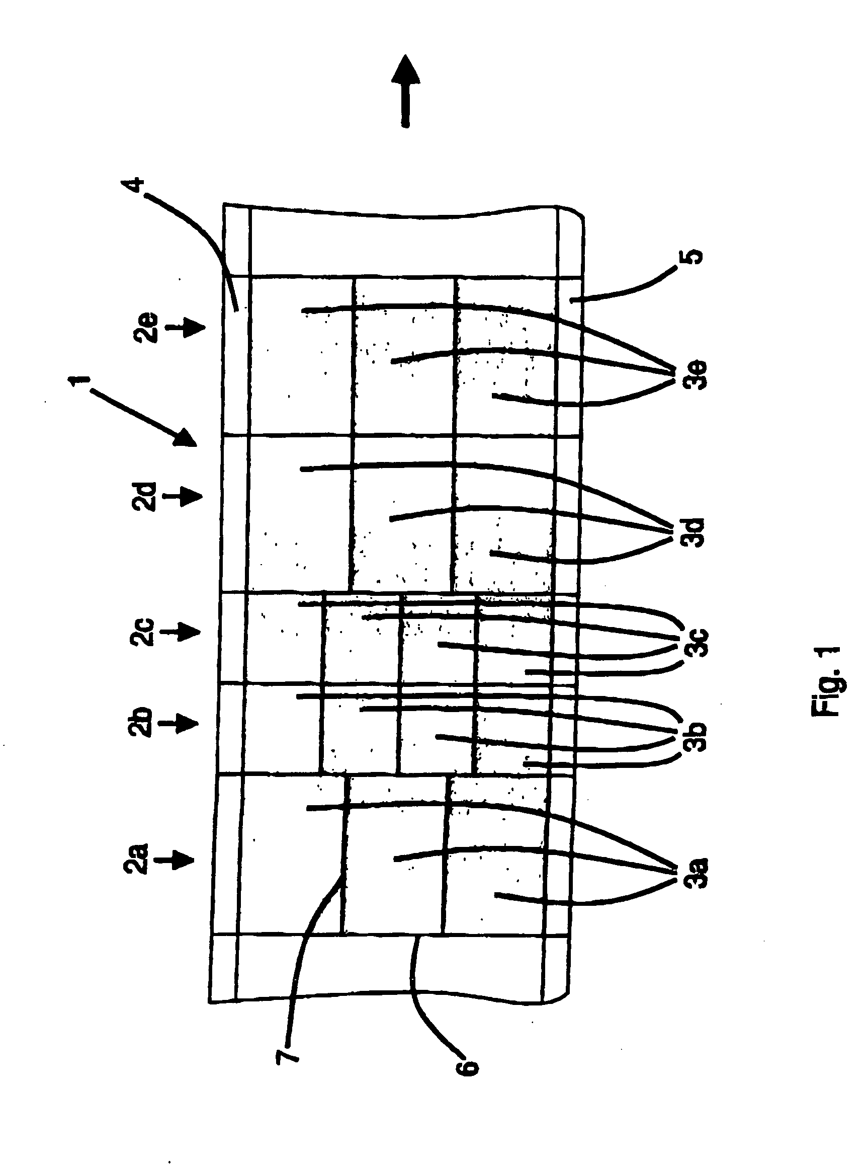
[0042] In FIG. 1 a continuously produced glass sheet 1 is shown, which is provided with a surface-covering cutting pattern. The cutting pattern holds or contains different-sized cutting glass panes 3a-3e. Each of the respective different-sized glass panes 3a-3e are arranged next to each other within one of the corresponding crosscut pieces 2a-2e. The cutting lines 6 extend between the individual crosscut pieces 2a-2e. The cutting lines 7 extend between the individual glass panes 3a-3e of an individual crosscut piece 2a-2e. The glass sheet 1 has a left border 4 and a right border 5, relative to the feed direction shown with the arrow. This sort of surface covering cutting pattern is suitable only for a fault-free glass sheet 1.

[0043] Each crosscut piece 2 shown in FIGS. 2a-2c is provided with three glass panes 3a-3c. The individual FIGS. 2a-2c have faults shown at different fault locations.

[0044] The glass fault 10 is located in the center pane 3b in FIG. 2a, which must be sorted o...


PUM

PropertyMeasurementUnit
Widthaaaaaaaaaa
Thicknessaaaaaaaaaa
Sizeaaaaaaaaaa

Abstract

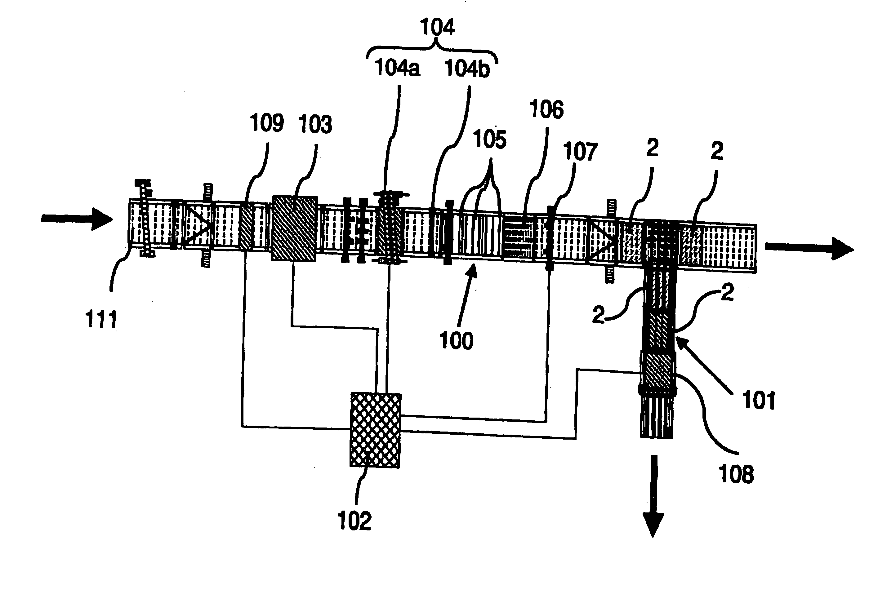
The method for cutting off glass panes from a continuously produced glass sheet includes continuously testing the glass sheet for glass faults prior to the cutting off process and determining glass sheet regions to be discarded containing the glass faults. Based on the test results for the glass faults an optimized cutting pattern for a predetermined glass sheet section is calculated in a cutting optimization device, which is a plan for cutting the glass sheet section into crosscut pieces, in which glass panes of respective sizes are arranged next to each other in corresponding crosscut pieces. In order to reduce waste, the cutting lines for the glass panes to be cut away within each crosscut piece are placed sufficiently close to the fault-containing glass sheet regions, so that widths (BS) of the glass sheet regions to be discarded are minimized or the glass sheet regions to be discarded are minimized, while accounting for a largest possible number of usable glass panes. The crosscut pieces are subsequently cut according to the optimized cutting pattern and the glass panes are formed. An appropriate apparatus for performing the method is described.

Description

BACKGROUND OF THE INVENTION [0001] 1. Field of the Invention [0002] The present invention relates to a method of cutting off glass panes or panels, especially rectangular glass panes or panels, from a continuously produced glass sheet, in which the glass sheet is continuously tested for glass faults prior to the cutting process and the glass sheet regions containing the glass faults or defects are determined and from the results of the fault detection an optimized cutting pattern for a given glass sheet section is determined in a cutting optimizing device. The cutting pattern comprises a plan for cutting the glass panes or panels into crosscut pieces and for cutting away glass panes of respective predetermined sizes arranged next to each other in corresponding ones of said crosscut pieces. [0003] The invention also relates to an apparatus for cutting off the glass panes from the glass sheet including a conveying device for the glass sheet and for the crosscut pieces cut from it, a f...

Claims


Application Information

Patent Timeline
IPC IPC(8): C03B33/023C03B33/02C03B33/03C03B33/037G01N33/38G06K1/00
CPCC03B33/037C03B33/0235G05B2219/35162Y10T83/04Y10T83/0448Y10T83/0524Y10T83/0538Y10T83/141Y10T83/155C03B33/023
Inventor BENISCHKE, PETERLEXOW, KLAUS-PETERWERNER, AXEL
Owner SCHOTT AG
Learn More