
Toroidal-coil linear stepping motor, toroidal-coil linear reciprocating motor, cylinder compressor and cylinder pump using these motors

a technology of linear stepping motors and reciprocating motors, which is applied in the field of linear motors, can solve the problems of reducing positioning accuracy, increasing cost, and inability to change during use, and achieves the effect of high positioning accuracy

Inactive Publication Date: 2005-02-03
JAPAN SERVO CO LTD
View PDF10 Cites 53 Cited by
  • Summary
  • Abstract
  • Description
  • Claims
  • Application Information

AI Technical Summary

Benefits of technology

[0012] An object of the present invention is to solve the above-described problems of the conventional machines and to provide an improved toroidal-coil linear stepping motor, an improved toroidal-coil linear reciprocating motor that do not cause the side pull, do not has deviation of the magnetic flux and have high positioning accuracy. Further object of the present invention is to provide a compact cylinder compressor and cylinder pump using these motors.
[0035] According to the multi-phase toroidal-coil linear stepping motor of the present invention, since the cylindrical element faces the cylindrical armature in 360 degrees through an air gap in the radial direction, the side pull is not generated, which reduces the load on the guide mechanism.
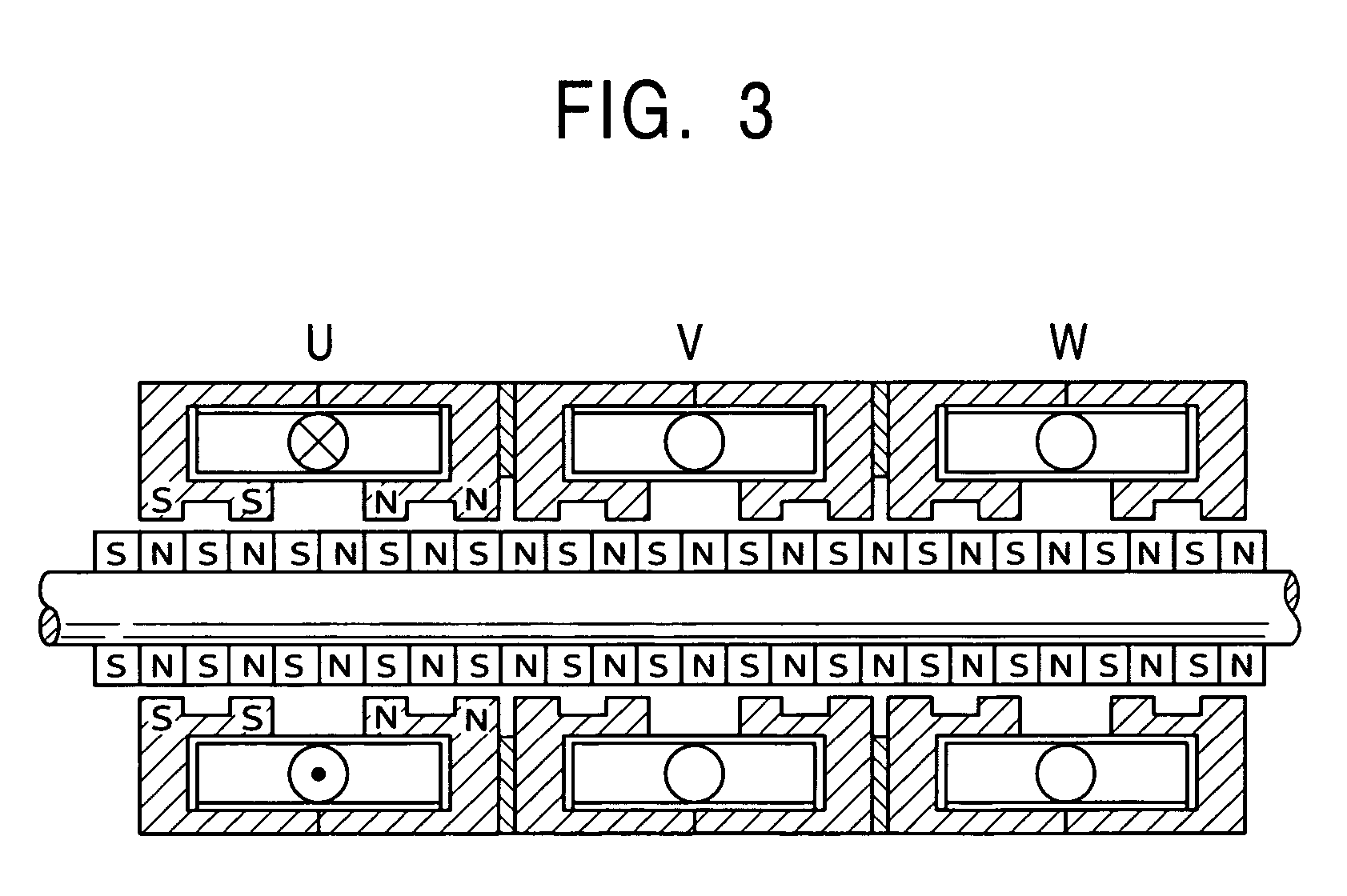
[0036] Further, since a permanent magnet is not arranged between the respective armature units, there is no deviation of the magnetic flux, which keeps high positioning accuracy. Particularly, when a surface magnet exposed to the air gap shown in (1-1), (1-2), (2-1) and (2-2) is used with a back yoke, the magnetic flux density can be balanced among the phases, which standardizes thrusts and increases positioning accuracy as compared with the embedded permanent magnet in the prior art shown in FIG. 28.
[0037] On the other hand, the single-phase toroidal-coil linear reciprocating motor of the present invention can simplify the structure rather than the multi-phase motor. Further, applying an alternating current to the single-phase toroidal coil, a movable portion vibrates. When a linear motor is used as a driving source of a compressor, the single-phase motor has higher efficiency and lower cost than the multi-phase motor. That is, a composite thrust of the multi-phase motor driven by a multi-phase excitation is not equal to the sum of the thrusts of the respective phase. For example, the efficiency in two-phase excitation is equal to {fraction ({square root}{square root over (2)})} / 2 (about 70%) for the multi-phase motor. On the other hand, the efficiency of the single-phase motor is about 100% in theory because it is always driven by a single-phase excitation.
[0038] According to the cylinder compressor of the present invention, since the axis fixed to the cylindrical element is connected to the pistons, the cylinders of the compressor can be used as bearings, which negates the needs for a guide mechanism in the linear motor, making the compressor compact as a whole. Still further, the similar construction can be used as a pump.

Problems solved by technology

Accordingly, the one-side-facing type linear stepping motor disclosed in the publication requires a guide mechanism such as the wheel 3 for the movable body 4 and a mechanism such as a linear bearing to receive the side pull so that the side pull dose not prevents the linear movement of the movable body, which increases the cost because of a complex mechanism.
This breaks the balance between thrusts of the respective phases, which lowers the positioning accuracy.
However, the inclination angle is determined at a manufacturing stage for each product and it cannot be changed during use.
Further, a complicated wobble action applies large mechanical stress on the mechanism, which shortens useful life of the mechanism.
However, if a piston of a compressor is only connected to a linear stepping motor, respective spaces for the cylinder and the linear stepping motor are necessary, and a mechanism for guiding a movable portion is required inside the linear stepping motor, which hinders from making the device compact.

Method used


Image

  • Toroidal-coil linear stepping motor, toroidal-coil linear reciprocating motor, cylinder compressor and cylinder pump using these motors
  • Toroidal-coil linear stepping motor, toroidal-coil linear reciprocating motor, cylinder compressor and cylinder pump using these motors
  • Toroidal-coil linear stepping motor, toroidal-coil linear reciprocating motor, cylinder compressor and cylinder pump using these motors

Examples


first embodiment

[0069] First Embodiment

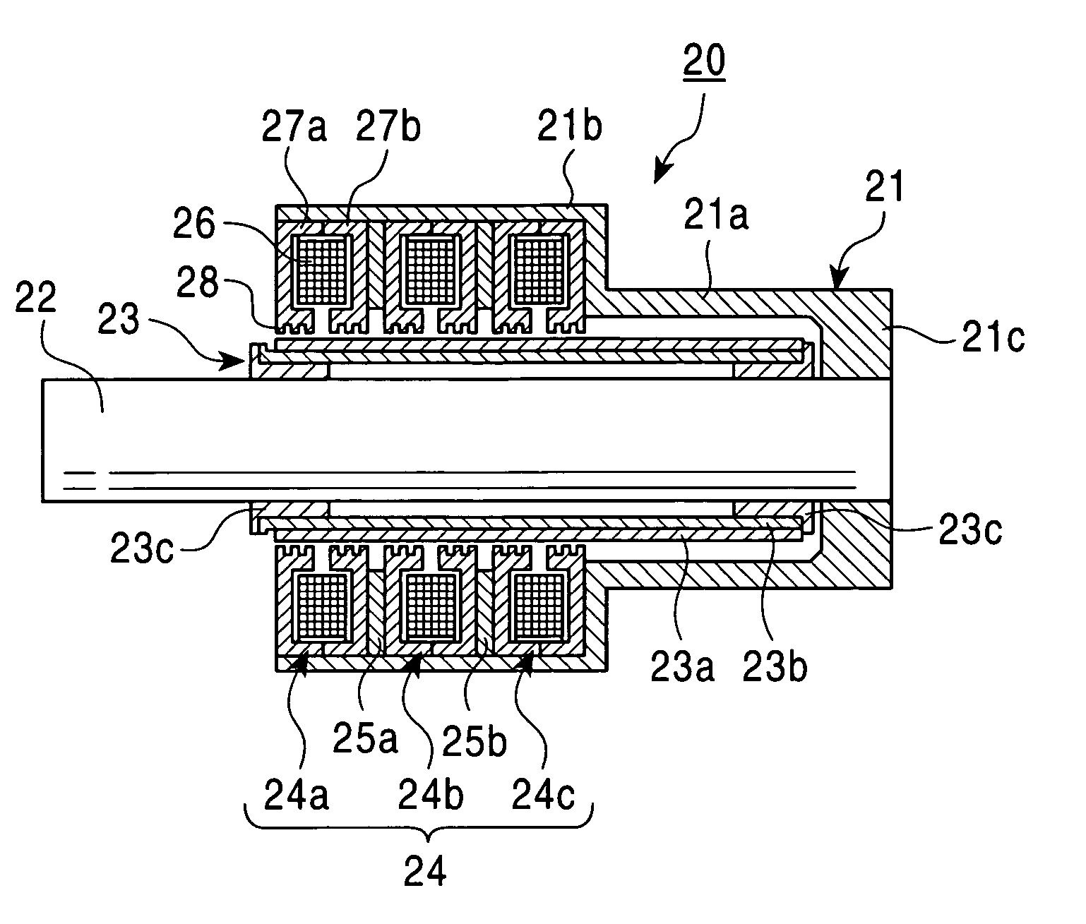
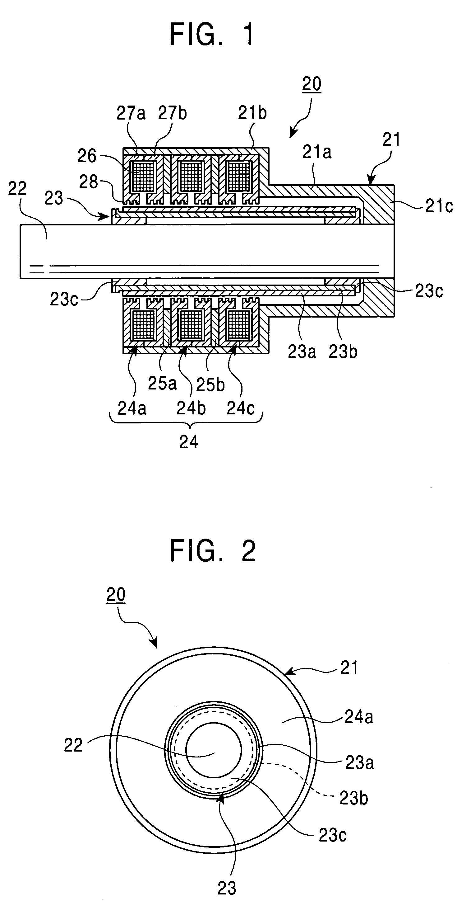
[0070]FIG. 1 is a sectional view of the toroidal-coil three-phase linear stepping motor according to the first embodiment and FIG. 2 is a front view of the motor in FIG. 1. The toroidal-coil three-phase linear stepping motor 20 of the first embodiment is provided with a cylindrical housing 21 that consists of a small-diameter portion 21a and a large-diameter portion 21b connected to each other, an axis 22 coaxially arranged inside the housing 21, a cylindrical element 23 that is supported by the axis 22 and an armature 24 that is fixed to the housing 21 around the cylindrical element 23 through an air gap in the radial direction. The cylindrical element 23 can linearly move along the axis 22.

[0071] The axis 22 is inserted and fixed into a holding hole formed on a bottom wall 21c that stops up the end of the small-diameter portion 21a of the housing 21. The cylindrical element 23 has toroidal permanent magnets 23a that are alternately magnetized in N pole and ...

second embodiment

[0083] Second Embodiment

[0084]FIG. 5 is a sectional view of a toroidal-coil two-phase linear stepping motor 30 according to the second embodiment, and FIG. 6 is a front view of the motor 30. The toroidal-coil two-phase linear stepping motor 30 of the second embodiment is provided with an axis 31 fixed to a housing (not shown), a cylindrical element 32 that is supported by the axis 31 and an armature 33 that is fixed to the housing (not shown) around the cylindrical element 32 through an air gap in the radial direction. The cylindrical element 32 can linearly move along the axis 31. The magnetic structure of the cylindrical element 32 has toroidal magnetic teeth 32a that are formed on the outer surface by alternately repeating projections and depressions in the axial direction. Further, the cylindrical element 32 is provided with bearings (not shown) in the same manner as the first embodiment.

[0085] Still further, the armature 33 consists of a pair of armature units 33a, 33b arrange...

third embodiment

[0090] Third Embodiment

[0091]FIG. 8 is a sectional view of a toroidal-coil single-phase linear reciprocating motor 40 according to the third embodiment, and FIG. 9 is a front view of the motor 40. The toroidal-coil single-phase linear reciprocating motor 40 of the third embodiment is provided with an axis 41 that is supported by a housing (not shown), a cylindrical element 42 fixed to the axis 41 and an armature 43 that is fixed to the housing (not shown) around the cylindrical element 42 through an air gap in the radial direction. The axis 41 can linearly reciprocate with respect to the housing (not shown). The cylindrical element 42 is made from magnetic material and has a pair of toroidal magnetic teeth 42a, 42b at both ends to form as a spool. The housing of the motor in FIG. 8 can be constructed in the same manner as FIG. 10.

[0092] The armature 43 consists of a single armature unit, it has a toroidal coil 44, a pair of armature yokes 45a, 45b with flanges that hold the toroida...


PUM


Abstract

A toroidal-coil multi-phase linear stepping motor includes a cylindrical housing, an axis coaxially arranged inside the housing, a cylindrical element supported by the axis and an armature fixed to the housing around the cylindrical element through an air gap in the radial direction. The axis is fixed to the housing and the cylindrical element linearly moves along the axis. The cylindrical element has toroidal permanent magnets that are alternately magnetized in N pole and S pole in the axial direction. The armature consists of armature units arranged around the axis. Each armature unit has a toroidal coil and a pair of armature yokes that hold the toroidal coil. Each armature yoke has toroidal magnetic teeth on its inner surface. The invention also includes a toroidal-coil single-phase linear reciprocating motor and a cylinder compressor and a cylinder pump using these motors.

Description

BACKGROUND OF THE INVENTION [0001] 1. Field of the Invention [0002] The present invention relates to a linear motor that is available to be used in various industrial devices. Particularly, the present invention relates to a toroidal-coil linear stepping motor and a toroidal-coil linear reciprocating motor that have toroidal coils in their armatures. Further, the present invention relates to a cylinder compressor and a cylinder pump using such a linear stepping motor or a linear reciprocating motor. [0003] 2. Prior Art [0004] Japanese unexamined patent publication Hei 10-191619 discloses a conventional linear stepping motor. FIG. 4 of the publication discloses a construction where a movable body 4 having wheels 3 slides on a linear rail 1 on which many stator teeth 2 are formed. Each of cores 8a and 8b of the movable body 4 is provided with small teeth 9 that face the stator teeth 2. When an electric current is applied to coils 28 and 28 that are wound around the respective cores in...

Claims


Application Information

Patent Timeline
IPC IPC(8): H02K33/16H02K41/03
CPCH02K41/03H02K33/16
Inventor SAKAMOTO, MASAFUMI
Owner JAPAN SERVO CO LTD
Learn More