Self-charging organic electroluminescent display device

a display device and organic technology, applied in the field of organic electroluminescent display devices, can solve the problem that solar cells cannot be charged at the same time when the display is in use, and achieve the effect of reducing the cost of mass production, reducing volume and weight, and effectively controlling the charging function of solar cells

Inactive Publication Date: 2005-02-03
IND TECH RES INST
View PDF6 Cites 36 Cited by
  • Summary
  • Abstract
  • Description
  • Claims
  • Application Information

AI Technical Summary

Benefits of technology

[0012] Besides, the solar cell and the organic electroluminescent display are formed on the same or different substrates. Using an external loop, the invention can effectively control the charging function of the solar cell and the uses of the organic electroluminescent display. The organic electroluminescent display and the solar cell have similar manufacturing processes in materials and structures. Thus, the cost for mass production can be lowered.
[0013] Combining the solar cell and the organic electroluminescent display has the advantages of minimizing volumes and weights. A large substrate can be simultaneously formed with many sets of solar cells and organic electroluminescent displays, very suitable for making outdoor advertising panels. The organic solar cell is formed by stacking more than one set of organic solar cell unit in order to increase the photoelectric conversion efficiency.

Problems solved by technology

Therefore, when the light-emitting device and the solar cell are combined using a common negative electrode, the solar cell cannot be charged at the same time when the display is in use.

Method used


Image

  • Self-charging organic electroluminescent display device
  • Self-charging organic electroluminescent display device
  • Self-charging organic electroluminescent display device

Examples


first embodiment

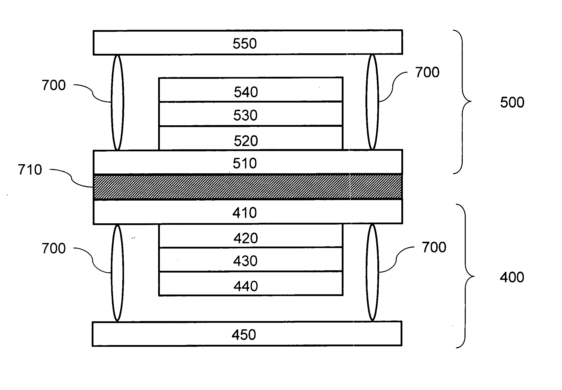
[0033]FIG. 5 shows the first embodiment of the disclosed self-charging organic electroluminescent display. The organic solar cell and the organic electroluminescent display are formed on two separate substrates, which are then packaged into a single display module.

[0034] The self-charging organic electroluminescent display includes an organic solar cell 400 and an organic electroluminescent device 500. The organic solar cell 400 is comprised of a first substrate 410, a conductive film 420 as a positive electrode, an organic solar energy absorption film 430, and a conductive film 440 as a negative electrode. The organic electroluminescent device 500 is comprised of a second substrate 510, a conductive film 520 as a positive electrode, an organic electroluminescent film 530, and a conductive film 540 as a negative electrode.

[0035] In the organic solar cell 400, the first substrate 410 is made of glass, plastic, or ceramic materials. The positive electrode film 420 is made of ITO or ...

second embodiment

[0046] Please refer to FIG. 9 for the second embodiment of the invention. An organic solar cell and an organic electroluminescent display are formed in different areas of the same substrate.

[0047] The organic solar cell 400 includes a common substrate 411, a positive electrode film 420, an organic solar energy absorption film 430, and a negative electrode film 440. The organic electroluminescent device 500 is similarly formed in a distinct area on the same surface of the sharing substrate 411. It further contains a positive electrode film 520, an organic electroluminescent film 530, and a negative electrode film 540.

[0048] The manufacturing process goes as follows. The positive electrode film 420, the organic solar energy absorption film 430, and the negative electrode film 440 are formed in order on the common substrate 411, forming the organic solar cell 400. In another area of the same substrate, the positive electrode film 520, the organic electroluminescent film 530, and the ...

third embodiment

[0052] Please refer to FIG. 11 for the third embodiment of the invention. An organic solar cell and an organic electroluminescent display are formed in the same area of a substrate.

[0053] The organic solar cell 400 includes a common substrate 411, a positive electrode film 420, an organic solar energy absorption film 430, and a negative electrode film 440. The organic electroluminescent device 500 contains a positive electrode film 520, an organic electroluminescent film 530, and a negative electrode film 540.

[0054] The manufacturing process goes as follows. The positive electrode film 420, the organic solar energy absorption film 430, and the negative electrode film 440 are formed in order on the common substrate 411, forming the organic solar cell 400. An opaque insulating layer 460 is formed above the conductive film 440 by evaporation. Afterwards, the positive electrode film 520, the organic electroluminescent film 530, and the negative electrode film 540 are coated in order, ...


PUM


Abstract

A self-charging organic electroluminescent display is disclosed. A solar cell and an organic electroluminescent device are installed on a same substrate or different substrates. Using the photoelectric conversion property of the solar cell, the solar energy is converted into electrical energy and stored in a battery. Therefore, the electrical energy converted from the solar energy can be provided for the organic electroluminescent device to emit light, forming a self-charging organic electroluminescent display module.

Description

BACKGROUND OF THE INVENTION [0001] 1. Field of Invention [0002] The invention relates to an organic electroluminescent display device and, in particular, to a self-charging organic electroluminescent display device. [0003] 2. Related Art [0004] The structure of an organic electroluminescent display 100 is shown in FIG. 1. It is mainly comprised of a substrate 110, a positive electrode 120, an organic electroluminescent film 130, a metal negative electrode 140, a glass packaging cover 150, and a packaging resin 160. When a voltage is imposed on the organic electroluminescent display, electrons and holes flow from the negative electrode 140 and the positive electrode 120 into the organic electroluminescent film 130 and combine into excitons there to emit light. [0005] The structure of an organic solar cell is shown in FIG. 2. It is mainly comprised of a substrate 210, a transparent positive electrode 220, an organic solar energy absorption film 230, a metal negative electrode 240, a g...

Claims


Application Information

Patent Timeline
Patent Type & Authority Applications(United States)
IPC IPC(8): G09F9/30H01L27/30H01L27/32H01L31/042H01L51/50H01L51/52H05B33/00
CPCH01L27/288H01L27/301H01L27/32H01L51/5237H01L31/042H01L51/50H01L27/3227H02S40/38Y02E10/50Y02E70/30H10K65/00H10K39/10H10K59/60H10K59/00H10K50/00H10K50/841
Inventor LEE, RONG-HOLU, CHUN-TE
Owner IND TECH RES INST
Why Eureka
Try Eureka