
Combined ultra wideband Vivaldi notch/meander line loaded antenna

a technology of vivaldi notch and notch, which is applied in the direction of antennas, slot antennas, antenna feed intermediates, etc., to achieve the effect of reducing low frequency cut-off, eliminating the possibility of creating grating lobes, and ultra wideband results

Inactive Publication Date: 2005-02-03
BAE SYST INFORMATION ELECTRONICS INTEGRATION
View PDF15 Cites 21 Cited by
  • Summary
  • Abstract
  • Description
  • Claims
  • Application Information

AI Technical Summary

Benefits of technology

The patent describes a new method for creating an ultra wideband antenna that can work over a wide range of frequencies. The method combines two technologies, a Vivaldi notch antenna and a meander line loaded antenna structure. By combining these two elements, the antenna can work over a wide range of frequencies without creating grating lobes. The Vivaldi notch is the active radiator at higher frequencies, while the meander line loaded antenna structure can cancel out reactances at the low end of the frequency range. The transition region between the Vivaldi notch and the meander line loaded antenna is smooth, and there is no discontinuity in the array. The antenna can work over a range of frequencies and is efficient at the low end of the frequency range. Grating lobes are prevented from being generated, and the antenna is small in size. The combination of these two technologies allows for an ultra wideband antenna that works over a wide range of frequencies without creating grating lobes.

Problems solved by technology

The problem with such an arrangement is how to make the dipole work over a 10:1 frequency range of its own accord.

Method used


Image

  • Combined ultra wideband Vivaldi notch/meander line loaded antenna
  • Combined ultra wideband Vivaldi notch/meander line loaded antenna
  • Combined ultra wideband Vivaldi notch/meander line loaded antenna

Examples


Embodiment Construction

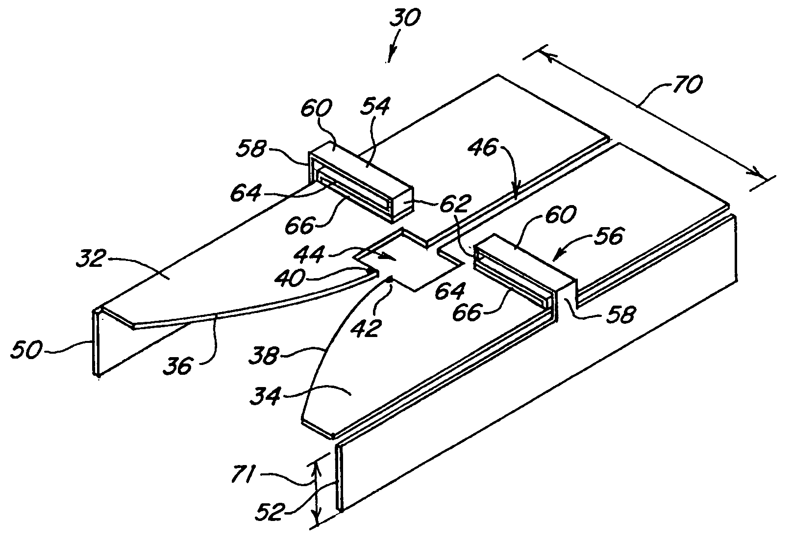
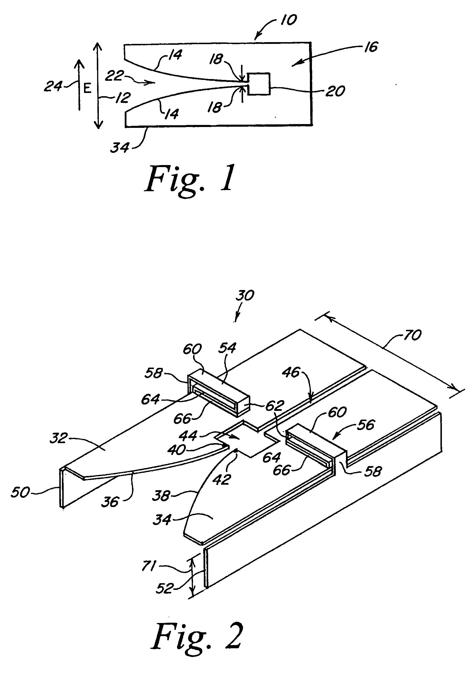
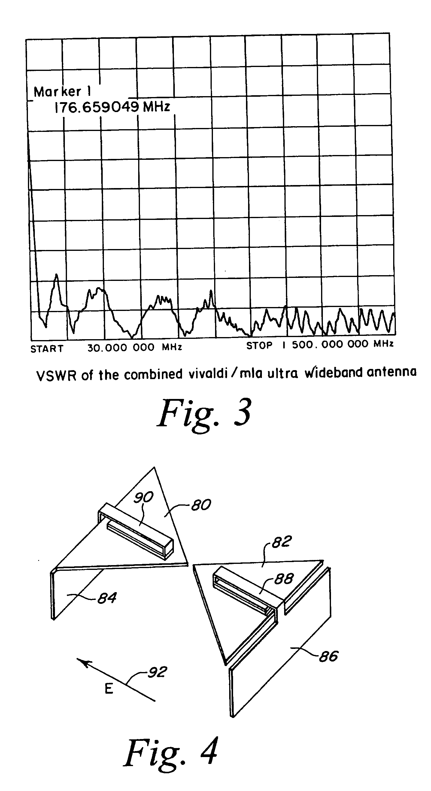
[0038] Referring to FIG. 1, a Vivaldi notch waveguide antenna 10 is illustrated as having an aperture 12 which is formed by exponentially shaped edges 14 in a plate 16. The antenna has a pair of feed points 18 which are adjacent the region of closest approximation of edges 14. Behind the feed point is a cavity 20, the purpose of which is to reflect back any rearwardly projecting radiation out through the notch which is defined by edges 14. The notch is therefore established by these edges as notch 22. Note that the E-field for the Vivaldi notch antenna Figure is as illustrated by arrow 24.

[0039] As mentioned hereinbefore, it is a feature of the Vivaldi notch antenna that its upper frequency cut-off is virtually unlimited. Thus it is typical for the Vivaldi notch antennas to operate from for instance from 100 MHz up to 10-20 GHz.

[0040] While this wide bandwidth operation is desirable, in some instance, the low frequency cut-off of such a Vivaldi notch antenna is restricted due to t...


PUM


Abstract

The combination of a Vivaldi slot and a meander line loaded antenna is provided which exhibits an ultra wideband characteristic with the Vivaldi notch expanding the high end and with the meander line loaded antenna portion reducing the low frequency cut-off. When these antennas are arrayed, this array exhibits a single lobe and an ultra wide 100:1 bandwidth. The Vivaldi notch portion of the antenna accommodates the higher frequencies, whereas the meander line loaded antenna portion of the antenna accommodates the lower frequencies, there being a smooth transition region between the Vivaldi and meander line portions of the antenna and no discontinuity. In one embodiment, the antenna is made to work between 50 MHz and 1500 MHz with a VSWR less than 3:1. The Vivaldi notch meander line combination assures that for an array one does not have a separation of the elements more than a 0.5 wavelength at the highest frequency, thus to eliminate the possibility of creating grating lobes. As one goes down in frequency to {fraction (1 / 50)} of the highest frequency, the 0.5 wavelength is divided by 50. This means that antenna element spacing is 0.01 wavelength at the low frequency end, clearly below that separation which would cause grating lobes. In short, the generation of grating lobes at the high end is prevented because the antenna element spacing is less than a 0.5 wavelength, with the situation improving as one goes down in frequency.

Description

FIELD OF INVENTION [0001] This invention relates to ultra wideband antennas, and more particularly to the utilization of a combined Vivaldi notch and meander line loaded antenna. BACKGROUND OF THE INVENTION [0002] There has long been a requirement for a very wide band array antenna to cover, for instance, a band of 100:1 or even 300:1. The purpose of such an antenna is for any ultra wideband application in which one seeks to have a single lobe from the antenna array uncorrupted by so called grating lobes which are the spurious lobes which are the result of standing waves in the elements and element spacings greater than 0.5 wavelength. [0003] An array of bow tie elements suffers from grating lobes introduced by the many periods of oscillation in the element itself, and by the resulting large spacing of the elements. [0004] In order to eliminate the generation of multiple lobes, one would need some sort of traveling wave antenna with a width less than 0.5 wavelength at the highest fr...

Claims


Application Information

Patent Timeline
Patent Type & Authority Applications(United States)
IPC IPC(8): H01Q9/26H01Q13/08H01Q21/30
CPCH01Q9/26H01Q21/30H01Q13/085
Inventor APOSTOLOS, JOHN T.
Owner BAE SYST INFORMATION ELECTRONICS INTEGRATION
Learn More