Display and driving method thereof

a technology of electroluminescent display and driving method, applied in static indicating devices, instruments, code conversion, etc., can solve the problems of limited current range and inability to uniformize images

Inactive Publication Date: 2005-02-03
SAMSUNG DISPLAY CO LTD
View PDF21 Cites 36 Cited by
  • Summary
  • Abstract
  • Description
  • Claims
  • Application Information

AI Technical Summary

Problems solved by technology

However, since the conventional sample/hold circuit uses TFTs as active devices for sampling and holding the current, the available current range is limited because of the TFT cha

Method used


Image

  • Display and driving method thereof
  • Display and driving method thereof
  • Display and driving method thereof

Examples


Embodiment Construction

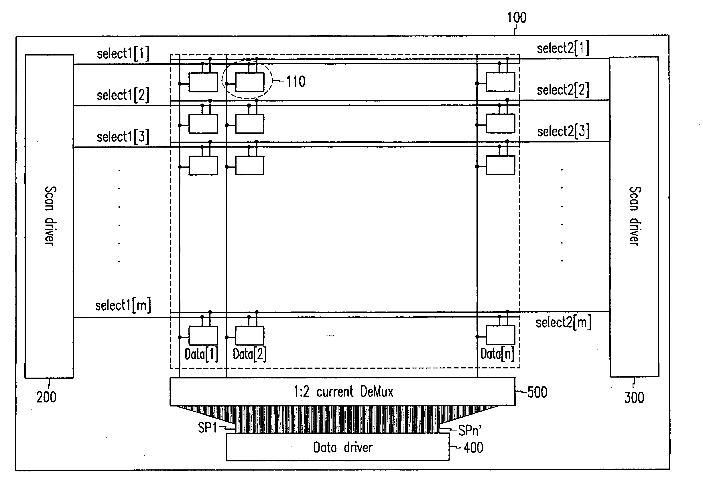
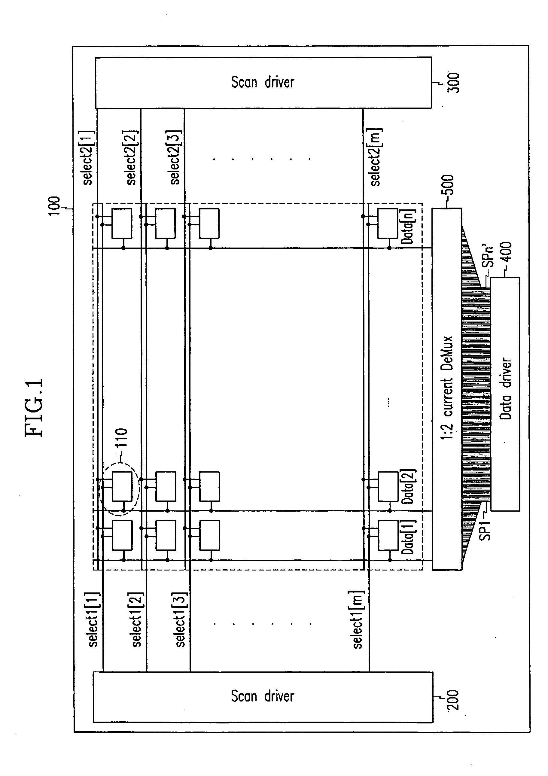
[0021]FIG. 1 shows a brief diagram of an organic EL display according to an exemplary embodiment of the present invention.

[0022] As shown, the organic EL display comprises organic EL display panel 100, scan drivers 200 and 300, data driver 400, and demultiplexer 500.

[0023] Organic EL display panel 100 comprises a plurality of data lines Data[1] to Data[n] for transmitting data signals that represent video signals, a plurality of scan lines select1[1] to select1[m] and select2[1] to select2 [m], and a plurality of pixel circuits 110. Data lines Data[1] to Data[n] transmit data signals that represent video signals to pixel circuits 110, scan lines select1[1] to select1[m] transmit select signals for selecting pixel circuits 110 to pixel circuits 110, and scan lines select2[1] to select2 [m] transmit emit signals for emitting light to pixel circuits 110. Pixel circuits 110 are respectively formed at a plurality of pixels surrounded by data lines Data[1] to Data[n] and scan lines sele...


PUM


Abstract

An organic electroluminescent display and driving method thereof. The organic electroluminescent display includes a demultiplexer for outputting signals provided by a data driver to a plurality of data lines according to on/off operation of analog switches. The driving method divides a frame into two parts, and drives them. Data signals are applied to pixels which are not adjacent among the pixels of each row during the former ½ frame, and the data signals are applied to the pixels to which no data signal has been applied in the former ½ frame during the latter ½ frame.

Description

CROSS REFERENCE TO RELATED APPLICATION [0001] This application claims priority to and benefit of Korea Patent Application No. 2003-52603 filed on Jul. 30, 2003 in the Korean Intellectual Property Office, the entire disclosure of which is incorporated herein by reference. BACKGROUND OF THE INVENTION [0002] (a) Field of the Invention [0003] The present invention relates to a display and a driving method thereof. More specifically, the present invention relates to an organic electroluminescent (EL) display and a driving method thereof. [0004] (b) Description of the Related Art [0005] In general, an organic EL display is a display device for electrically exciting fluorescent and organic compounds and emitting light therefrom, and voltage or current drives (M×N) organic emission cells to represent images. An organic emission cell includes an anode (indium tin oxide: ITO), an organic thin film, and a metallic cathode layer. The organic thin film includes an emission layer (EML), an electr...

Claims


Application Information

Patent Timeline
IPC IPC(8): H01L51/50G09G3/20G09G3/30G09G3/32H05B33/00H05B33/14
CPCG09G3/3283G09G2300/0861G09G2320/0223G09G2310/0297G09G2310/0224G09G3/30
Inventor SHIN, DONG-YONG
Owner SAMSUNG DISPLAY CO LTD
Why Eureka
Try Eureka