Graphic processing method and device

a graphic processing and program recording technology, applied in the field of graphic processing methods and devices, can solve problems such as ineffective methods, difficult to determine statistical significance concerning differences, and influence on quantization of differences between figures

Inactive Publication Date: 2005-02-03
KK TOSHIBA
View PDF11 Cites 22 Cited by
  • Summary
  • Abstract
  • Description
  • Claims
  • Application Information

AI Technical Summary

Problems solved by technology

A function of using a value of cross correlation described in the document as a scale of similarity between the images has been incorporated as a standard into an image processing system these days, but there has been a problem that the function is largely influenced by a fluctuation of light and shade of a whole image to be treated or noise.
In these methods, it can be judged whether or not there is a difference between a reference figure and an inspection object figure, but it has been difficult to determine statistical significance concerning the difference.
There has also been a problem that quantization of the difference between the figures is influenced by an error in positioning the figures.
However, there has been a problem that the method is not effective in a case other than a case wher...

Method used


Image

  • Graphic processing method and device
  • Graphic processing method and device
  • Graphic processing method and device

Examples


first embodiment

[0037] First Embodiment

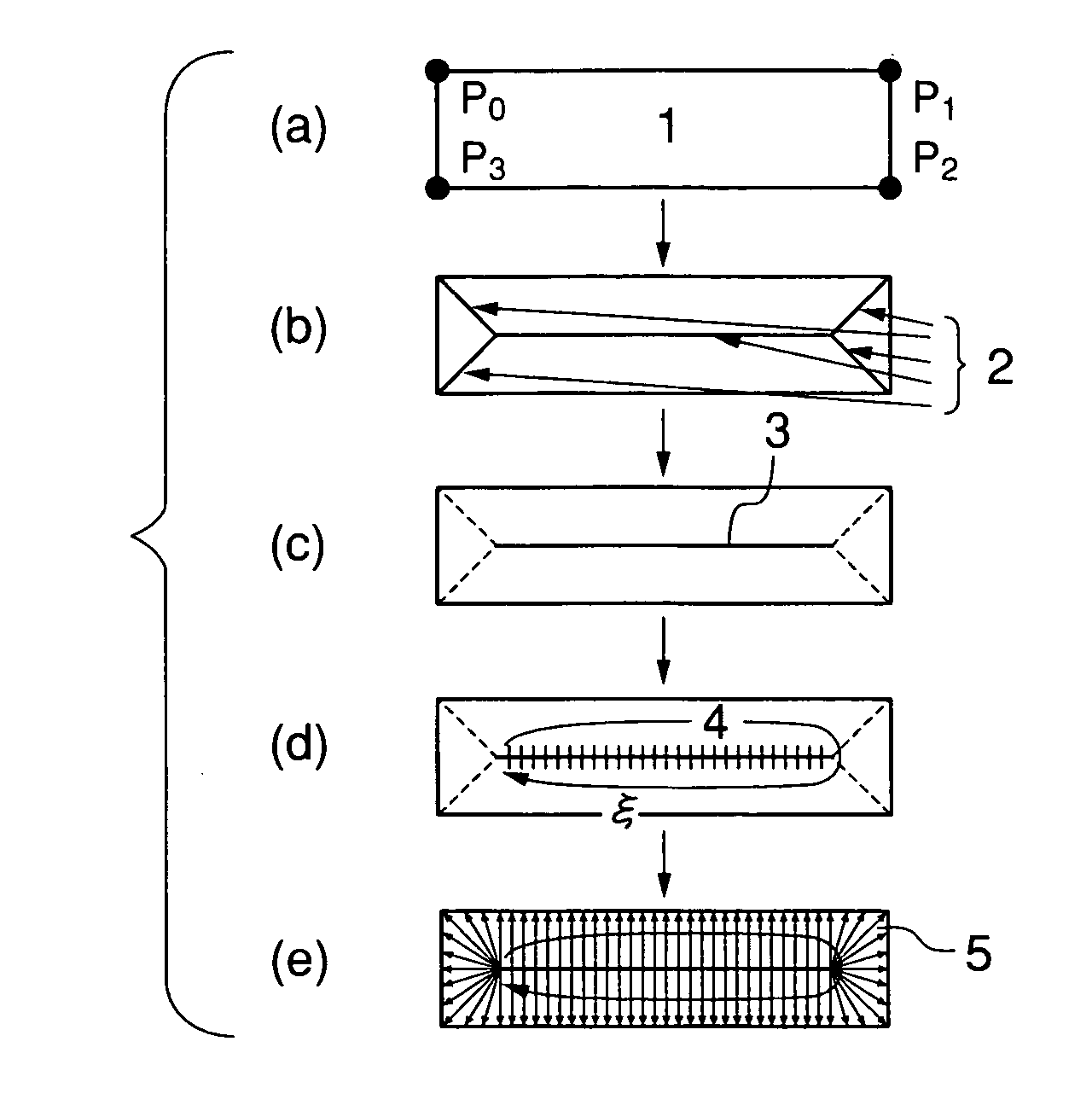
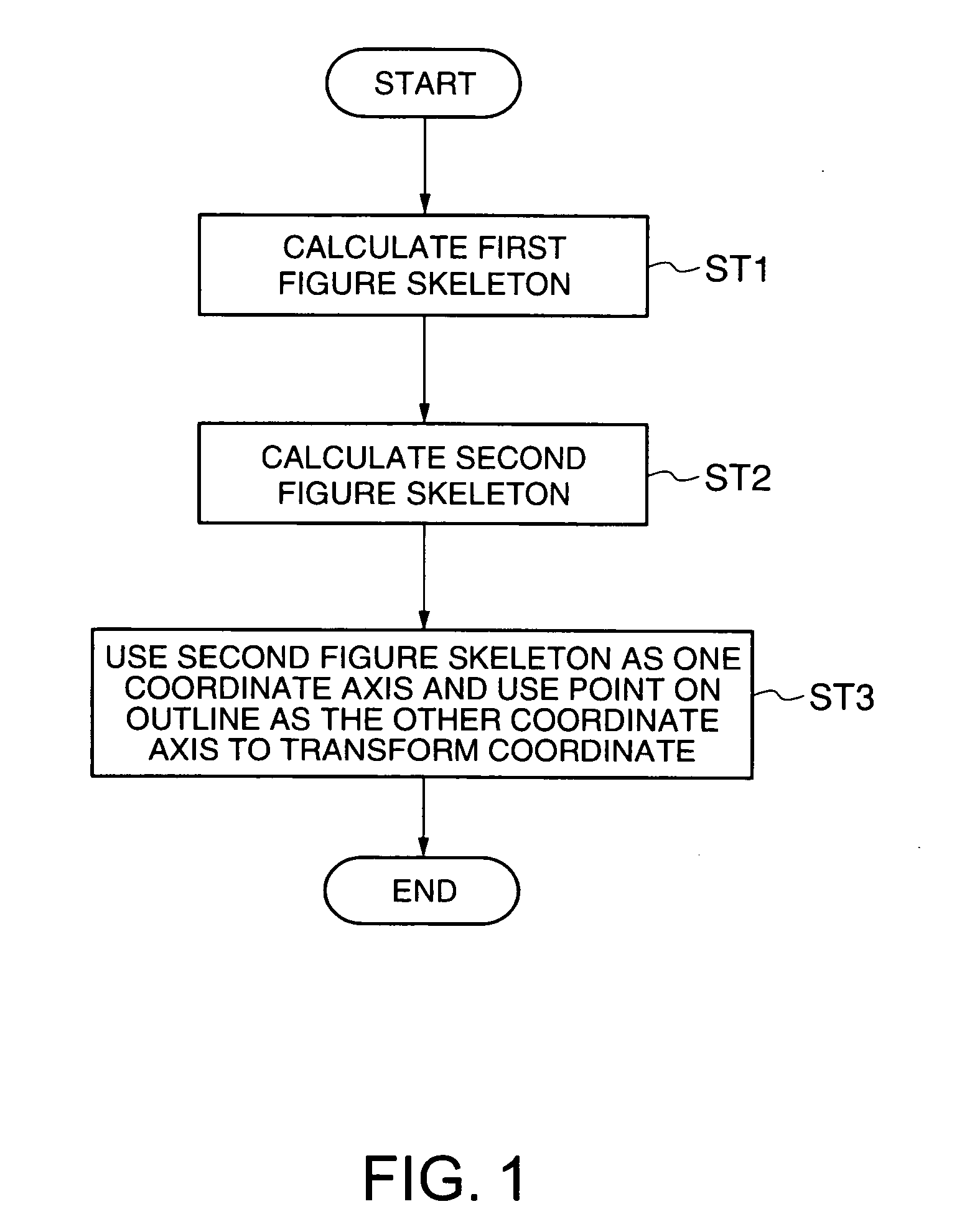
[0038] First, a basic constitution of a graphic processing method according to a first embodiment of the present invention will be described. In the graphic processing method according to a basic constitution, in a first step ST1, a first figure skeleton distant from an outline of a figure by each equal distance toward a center of the figure is calculated using at least one of a medial axis and a chordal axis with respect to the figure in which the outline of an object shape reflected in a digital image is represented by a set of points. Next, in a second step ST2, a branch line extending to the skeleton from a vertex of the figure is deleted from the first figure skeleton calculated by the first step ST1 to obtain a second figure skeleton. Next, in a third step ST3, with respect to data obtained by one circulation of the outline of the figure using one end point of the second figure skeleton obtained by the second step as a start point and using the other end...

second embodiment

[0051] Second Embodiment

[0052] Next, a graphic processing method according to a second embodiment of the present invention will be described. In the second embodiment, comparison of a CAD figure with an outline figure of a pattern extracted from a SEM image will be described. First, a pattern figure corresponding to a pattern constituting an inspection object is selected from design CAD data, and recorded as polygon data in the storage section 106 of FIG. 19 described later. This figure has a shape shown by a FIG. 14 in FIG. 8(a).

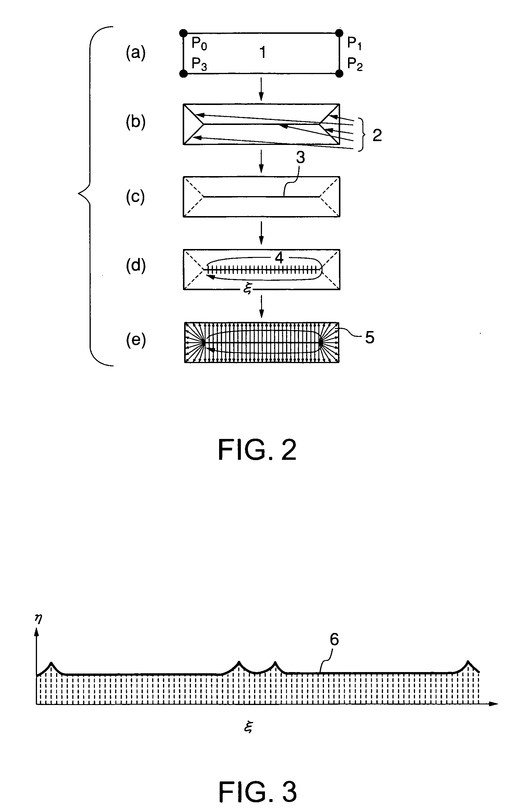
[0053] Subsequently, a medial axis is prepared with respect to this figure, and branches are pruned off from the figure as shown in FIG. 8(b). Next, one end of a skeleton 10 is used as a start point, and a new coordinate is defined as a coordinate axis ε on a line in a direction of one circulation around the skeleton (11 of FIG. 8(c)). Subsequently, a curve group 13 conjugated with curve groups 12 and 13 at an equal distance from the coordinate axis ε is c...

third embodiment

[0060] Third Embodiment

[0061] Next, a graphic processing method according to a third embodiment of the present invention will be described. In the third embodiment, a method of evaluation of agreement between two figures will be described. Values obtained by integrating both curves in the ε−η coordinate system obtained in the second embodiment along ε are plotted in the ordinate, and ε is plotted in the abscissa as shown in FIG. 11. Since a maximum value of a difference between the values of both curves normalized as ∫ηdε=1 in the corresponding ε coordinate corresponds to Kolmogorov-Smirnov statistic, the values are compared with a numerical table to calculate the agreement between the curves.


PUM


Abstract

There is disclosed a graphic processing method in which a first figure skeleton apart from an outline of a figure by each equal distance in a central direction of the figure is calculated using at least one of a medial axis and a chordal axis with respect to a figure representing the outline of the object shape reflected in a digital image by a set of points, branch lines to the skeleton from a vertex of the figure in the calculated first figure skeleton are removed to obtain a second figure skeleton, and a curve coordinate system is defined using the second figure skeleton as one coordinate axis and using a distance between the second figure skeleton and the outline of the figure as the other coordinate axis with respect to data obtained by one circulation of the outline of the figure using one end point of the second figure skeleton as a start point and using the other end point as a terminal point to transform the coordinate of points on the outline of the figure into the other coordinate axis of the curve coordinate system.

Description

CROSS REFERENCE TO RELATED APPLICATION [0001] This application is based upon and claims the benefit of priority from the prior Japanese Patent Application No. 2003-185365, filed on Jun. 27, 2003, and No. 2004-172752, filed on Jun. 10, 2004, the entire contents of which are incorporated herein by reference. BACKGROUND OF THE INVENTION [0002] 1. Field of the Invention [0003] The present invention relates to: a graphic processing method, device, and program recording medium; particularly a method for comparing shapes of figures; especially a shape comparison method and a shape inspection method in which outline shapes extracted from a digital image of an object acquired by a microscope or a digital image of a fine pattern acquired by an electronic microscope are compared or inspected; and further a graphic processing method including a program for realizing the method, a device, and a recording medium of a graphic processing program. [0004] 2. Background Art [0005] There have heretofor...

Claims


Application Information

Patent Timeline
IPC IPC(8): G06T7/00G06V10/46G06T3/00
CPCG06K9/48G06T2207/20044G06T7/606G06T7/0004G06T7/66G06V10/46
Inventor IKEDA, TAKAHIROHASHIMOTO, KOJIITO, TAKESHI
Owner KK TOSHIBA
Why Eureka
Try Eureka