
Three dimensional rendering including motion sorting

a three-dimensional rendering and motion sorting technology, applied in the field of visualization methods, can solve the problems of wasting valuable rendering power for drawing, many pixels are rendered unnecessarily, and the rendering pipeline has wasted a clock cycle rendering the old pixels, so as to reduce the number of primitives used to represent the moving object at run time.

Inactive Publication Date: 2005-02-03
ROUND ROCK RES LLC
View PDF20 Cites 29 Cited by
  • Summary
  • Abstract
  • Description
  • Claims
  • Application Information

AI Technical Summary

Benefits of technology

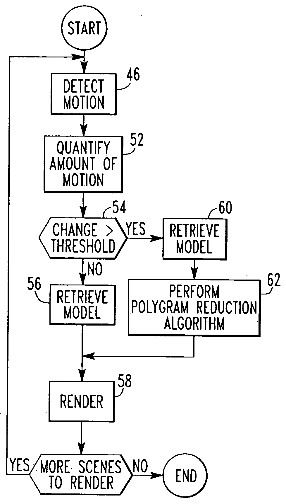
[0013] The present solves the problems of the prior art by providing a method of reducing at run time the number of primitives that need to be used to render an object. The method of the present invention determines that an object is moving within a scene. At run time, the number of primitives used to represent the moving object is reduced. The degree of reduction can be related to the amount of motion, i.e. speed, of the moving object. The moving object is then rendered based on the reduced number of primitives.
[0014] The present invention takes advantage of the fact that the human eye is less sensitive to the details of an object in motion, but rather is more sensitive to the motion itself. By identifying and quantifying the motion, the level of detail of the moving object can be reduced. By saving time and memory bandwidth by not rendering moving objects with the same level as detail as that of stationary objects, more rendering time and hence more detail can be added to the stationary items, leading to a more realistic image. The motion detecting aspect of the present invention can also be used to make decisions whether the moving object should be re-rendered, moved, or left as is. The present invention can be implemented in existing 3D rendering pipelines. Those, and other advantages and benefits, will be apparent from the Description of the Preferred Embodiments appearing hereinbelow.

Problems solved by technology

The problem, however, is that the rendering pipeline has wasted a clock cycle rendering the old pixel which has now been replaced by a new pixel.
Furthermore, even if the new pixel is rendered and stored, it is possible that a later triangle will happen to cover this pixel, again causing an overwrite.
Thus, it is seen that many pixels are rendered unnecessarily.
The rendering pipeline is wasting valuable rendering power for the drawing, or at least the processing, of pixels that will never be seen on the screen.
Each of those uselessly rendered pixels is taking away fill rate.
Another problem with rendering pixels that will not be seen in the final image is with the z buffer.
Such z buffer accesses cost an immense amount of memory bandwidth.
Even with culling and clipping, however, the number of triangles to be rendered in a highly detailed scene requires a tremendous amount of computing power and memory bandwidth.

Method used


Image

  • Three dimensional rendering including motion sorting
  • Three dimensional rendering including motion sorting
  • Three dimensional rendering including motion sorting

Examples


Embodiment Construction

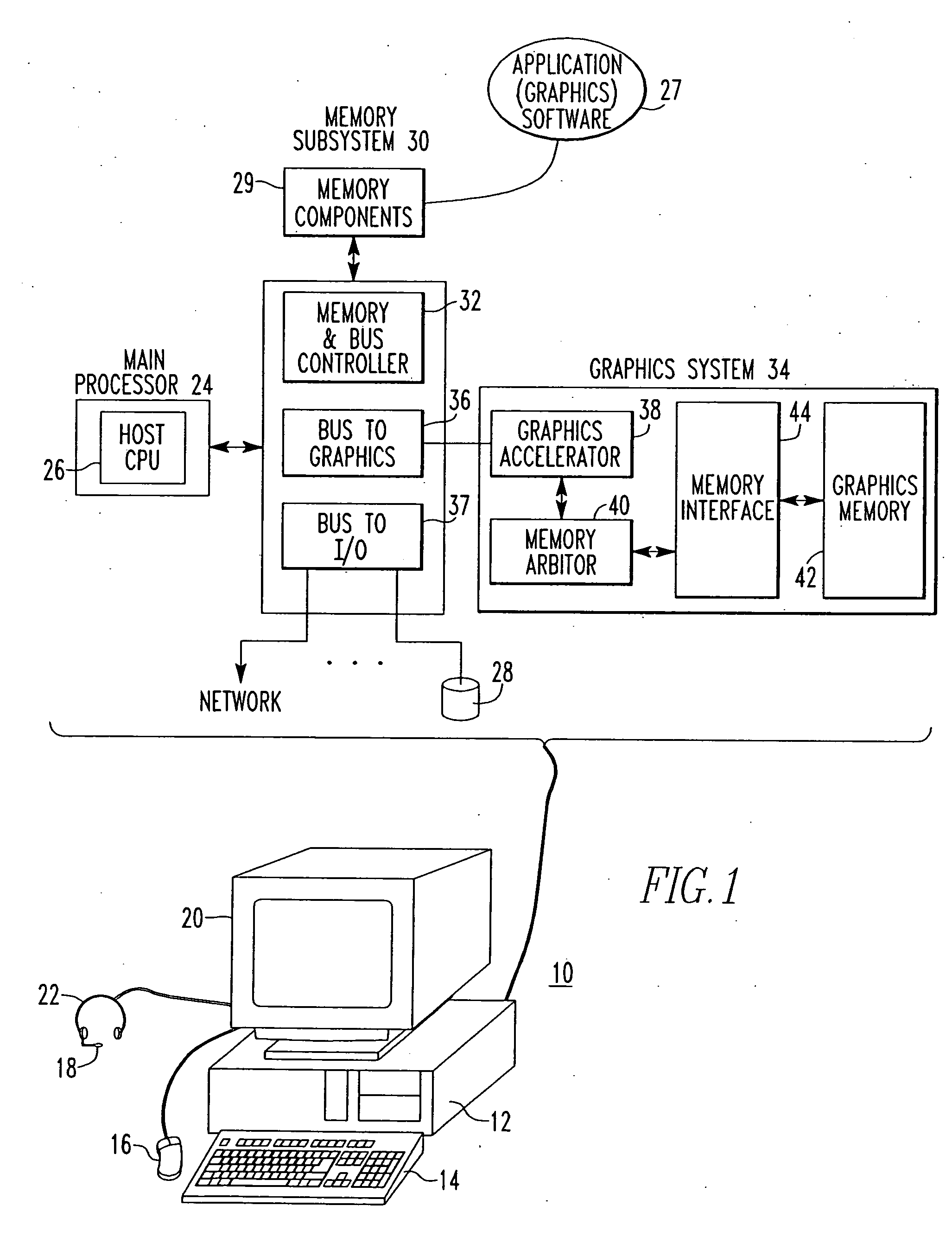
[0022]FIG. 1 is a block diagram of hardware 10 which may used to implement the present invention. The hardware 10 may be a personal computer system comprised of a computer 12 having as input devices keyboard 14, mouse 16 and microphone 18. Output devices such as a monitor 20 and speakers 22 may also be provided. The reader will recognize that other types of input and output devices may be provided and that the present invention is not limited by the particular hardware configuration.

[0023] Residing within computer 12 is a main processor 24 which is comprised of a host central processing unit 26 (CPU). Software applications, such as graphics software application 27, may be loaded from, for example, disk 28 (or other device), into main memory 29 from which the software applications 27 may be run on the host CPU 26. The main processor 24 operates in conjunction with a memory subsystem 30. The memory subsystem 30 is comprised of the main memory 29, which may be comprised of a number of...


PUM


Abstract

The present invention determines that an object is moving within a scene. At run time, the number of primitives used to represent the moving object is reduced. The degree of reduction can be related to the amount of motion, i.e. speed, of the moving object. The moving object is then rendered based on the reduced number of primitives saving time and memory bandwidth.

Description

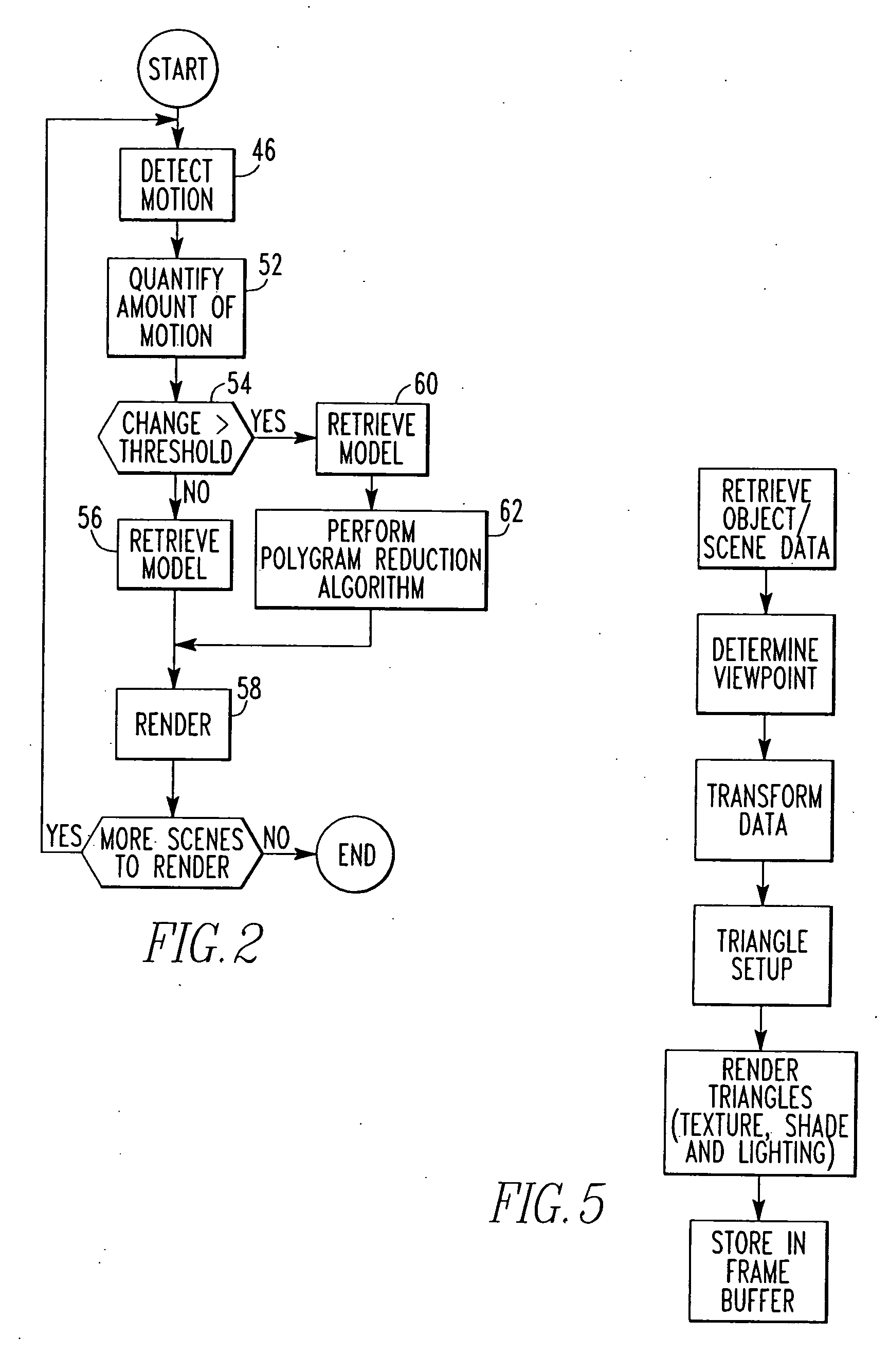
CROSS-REFERENCE TO RELATED APPLICATIONS [0001] The present invention is a continuation of pending U.S. application Ser. No. 09 / 902,981 entitled “Three Dimensional Rendering Including Motion Sorting” filed 11 Jul. 2001 and assigned to the same assignee as the present invention.BACKGROUND [0002] The present invention is directed to visualization methods and, more particularly, to three dimensional (3D) rendering techniques. [0003] 3D images are generated, or rendered, by 3D pipelines. A 3D pipeline may be represented as a series of steps such as those shown in FIG. 5. The steps are often implemented by an application program running on a computer, with or without specialized graphics acceleration hardware, in conjunction with memory devices. The memory devices store information about objects, lighting, view points, and other information needed to generate a 3D image. The goal of the rendering operation is to produce in a frame buffer a 2D image that is to be displayed on a monitor. [0...

Claims


Application Information

Patent Timeline
Patent Type & Authority Applications(United States)
IPC IPC(8): G06T15/00G06T17/20
CPCG06T7/20G06T2210/36G06T17/20G06T15/00G06T17/00
Inventor KLEIN, DEAN A.
Owner ROUND ROCK RES LLC
Learn More