Image capturing apparatus provided with image processor

a technology of image processing and image capturing apparatus, which is applied in the direction of instruments, television systems, color signal processing circuits, etc., can solve the problems of difficult to determine the white saturation level based on this convex portion, uniform illumination, and inability to obtain suitable -characteristics

Inactive Publication Date: 2005-02-03
MINOLTA CO LTD
View PDF4 Cites 28 Cited by
  • Summary
  • Abstract
  • Description
  • Claims
  • Application Information

AI Technical Summary

Benefits of technology

[0055] According to another aspect of the present invention, a method for controlling an image capturing apparatus provided with an illuminance nonuniformity corrector for performing an illuminance nonuniformity correction to

Problems solved by technology

Specifically, if the white board is assumed to be illuminated by ceiling lights of the room and sunlight coming through the windows, illuminance nonuniformity occurs due to a nonuniform illumination light.
If the block size in relation to the character size is improper, a suitable γ-characteristic cannot be obtained.
The convex portion corresponding to the white portion of the histogram of level-frequency distribution generated using the pixel data in the block becomes small and it is difficult to determine the white saturation level based on this convex portion.
Thus, it is difficult to stably set the white saturation level based on this convex portion.
Thus, there is a likelihood that the white level is erroneously detected based on the convex portion corresponding to the background portion.
This leads to a disadvantage that the white board portion of the block including the background portion turns black.
In the case that the white board is captured together with its background, the image quality is considerably reduced, making the image hard to be seen if the coloring phenomenon occurs in the white board portion in a boundary area between the white board portion and the background portion during the image processing, namely the illuminance nonuniformity correction.
Accordingly, the illuminance nonuniformity correction may not be performed even if the conventional γ-correction technique is applied to digital cameras.
Thus, even if this technique is applied to a picture image where the illuminance nonuniformity occurs in a two-dimensional manner, it is difficult to effectively correct the illuminance nonuniformity along main scanning direction.
However, since the histogram of level-frequency distribution of the pixel data is generated every block and the threshold value of the binary processing is set by neural network using the histogram of level-frequency distribution data, a complicated and cumbersome calculation is disadvantageously required to set the threshold value.
If the block size is set too small, the histogram of level-frequency distribution of the pixel data is improper and a suitable threshold value cannot be set.
Further, since a long time is disadvantageously required for the calculation due to a huge number of blocks, there should be a limit in the number of blocks.
Further, a calculation made to avoid the discontinuity of the image quality resulting from a difference between the processings applied to the blocks using different γ-characteristics is not easy.
Thus, a problem of the coloring phenomenon in the boundary area between the white board portion and the background portion is not considered at all and, hence, there is no indication or disclosure concerning this problem.
As a result, the illuminance nonuniformity correction causes a problem of coloring the white portion.
They neither disclose nor indicate the illuminance nonuniformity correction technique for a color image and the problem in the illuminance nonuniformity correction of the color image.
When characters and/or figures drawn on a white board in a conference hall are to be captured by an electronic camera provided with a built-in flash, the built-in flash is often automatically fired becaus

Method used


Image

  • Image capturing apparatus provided with image processor
  • Image capturing apparatus provided with image processor
  • Image capturing apparatus provided with image processor

Examples


first embodiment

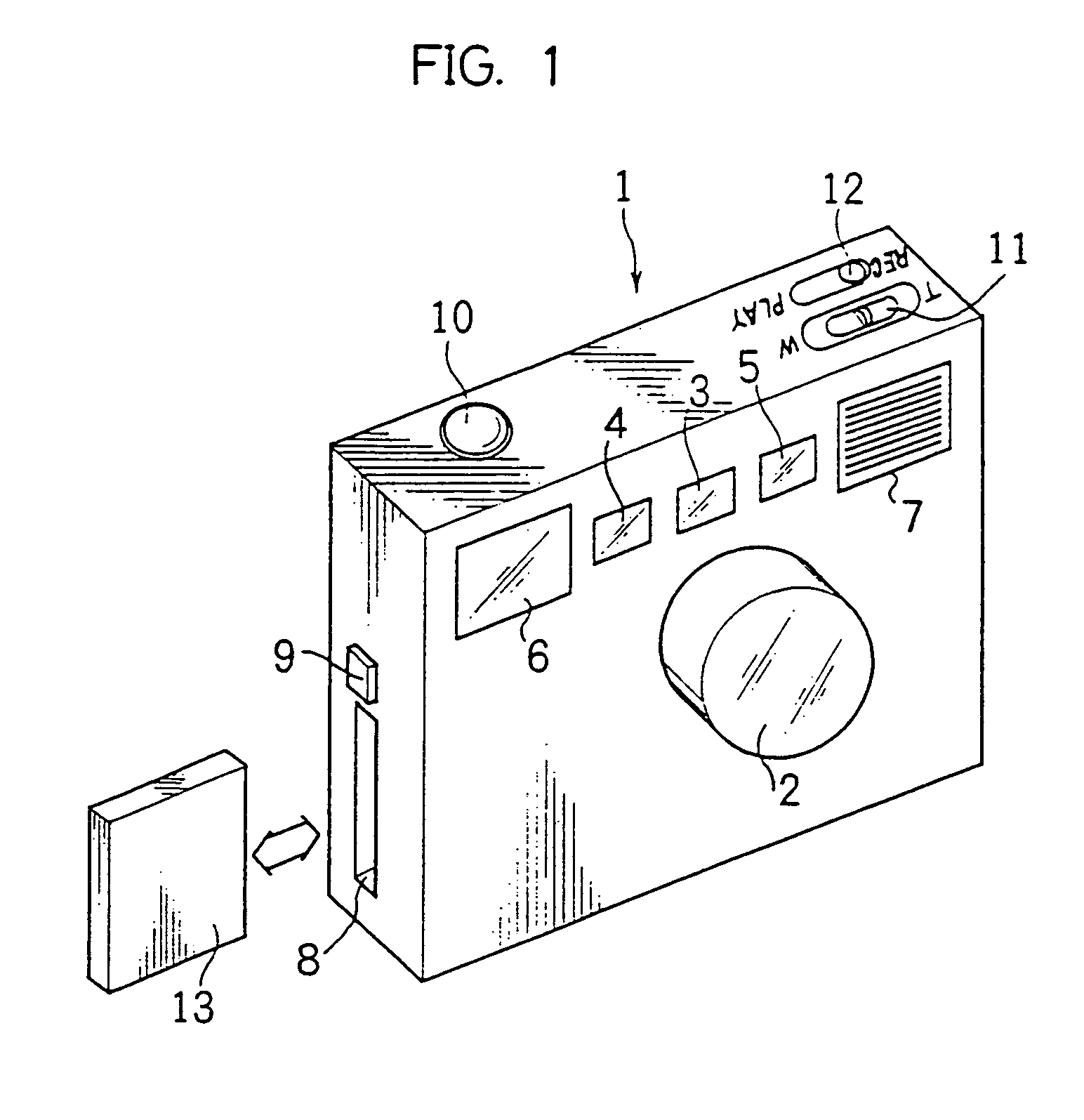
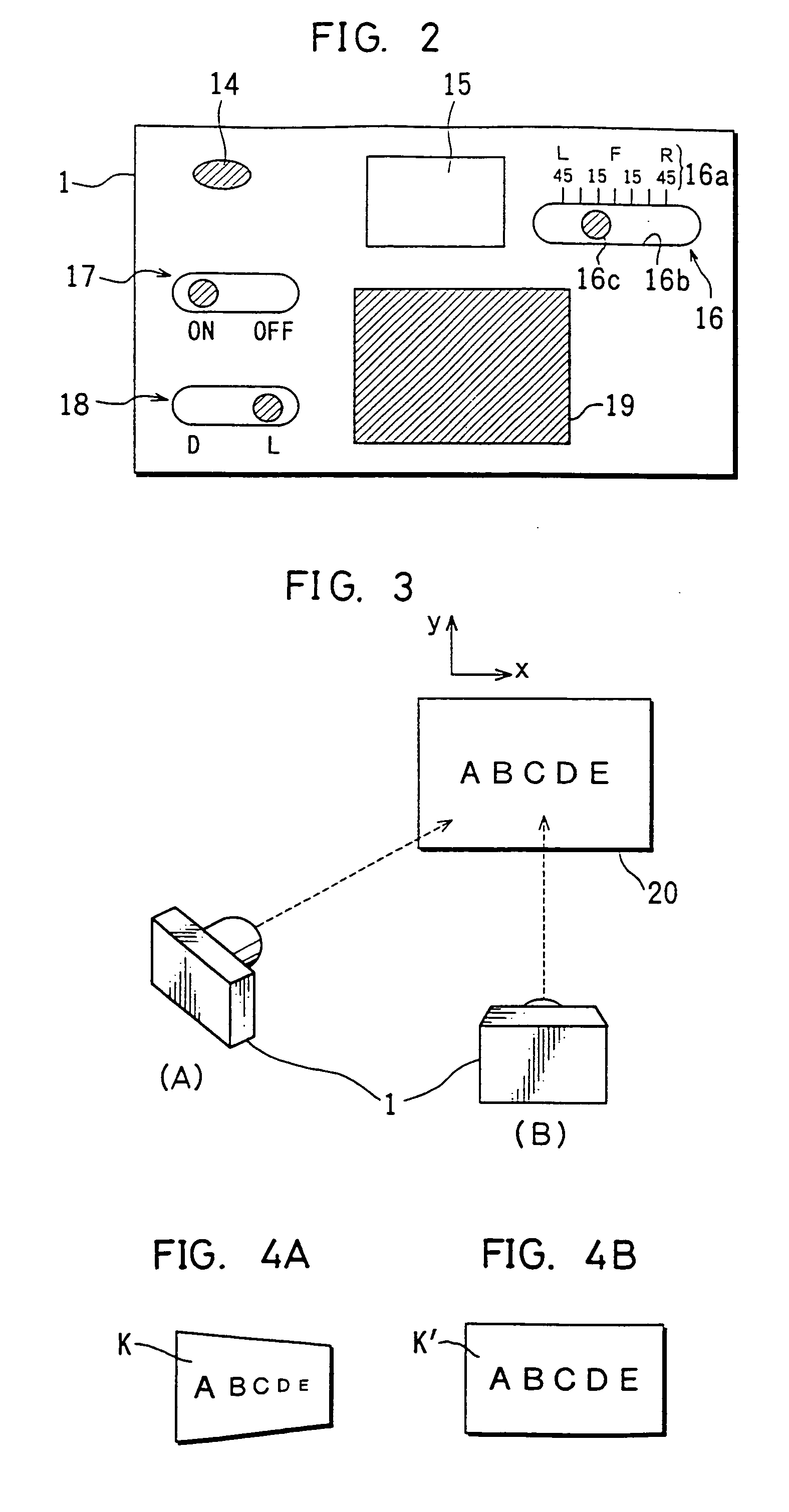
[0125]FIG. 1 is a perspective view showing an external configuration of an electronic camera according to the invention, and FIG. 2 is a rear view of this electronic camera.

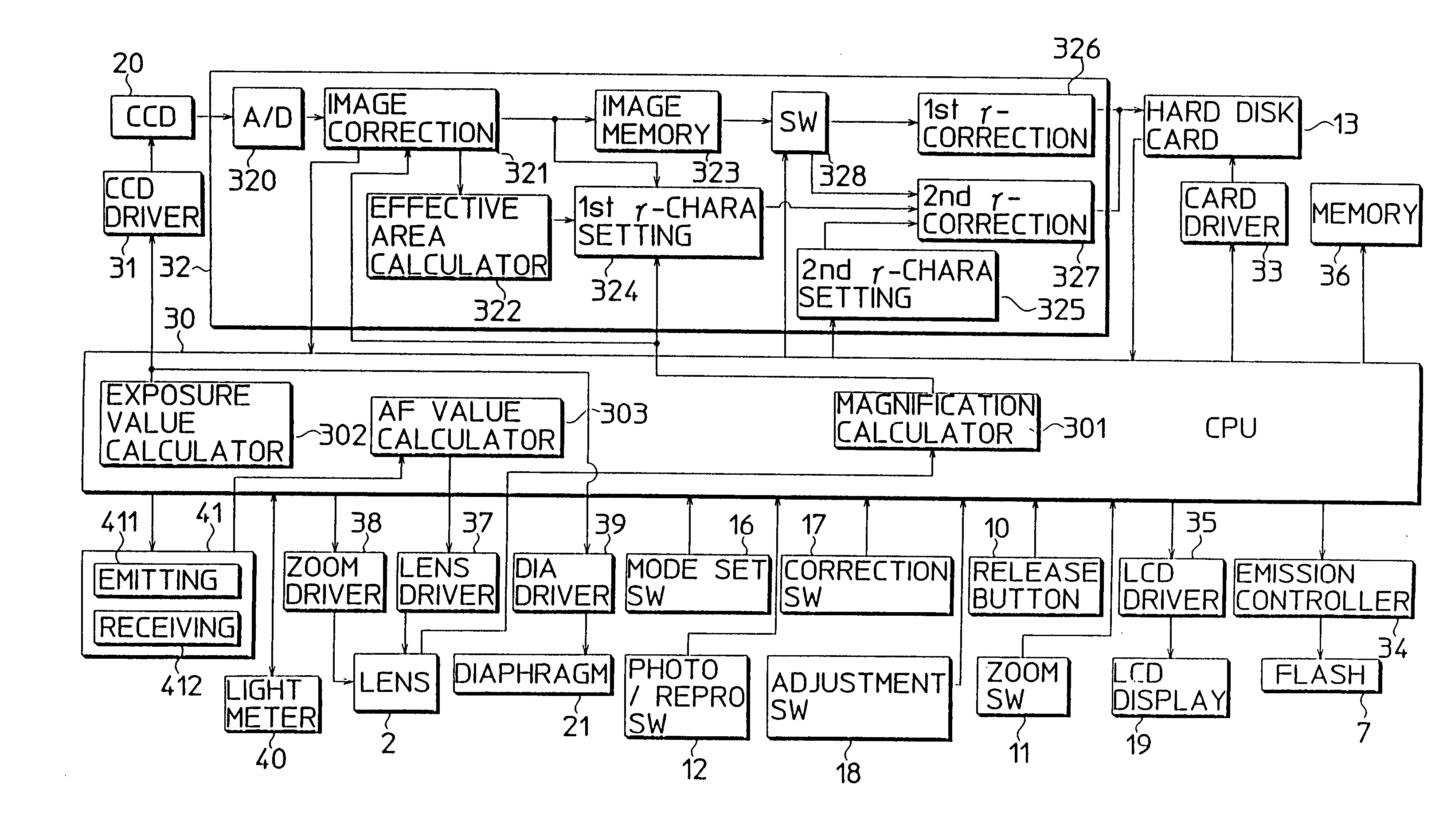
[0126] A camera 1 of FIGS. 1 and 2 includes a CCD area sensor as an image pickup device. An image data sensed by this CCD area sensor is recorded in an unillustrated hard disk card of PCMCIA standards. Although a case where the area sensor is used as an image pickup device is described in this embodiment, an image data may be picked by scanning an object light image by a line sensor.

[0127] The camera 1 is provided with a function of correcting an image of an object whose surface is not parallel with the sensing surface of the CCD area sensor (hereinafter, “oblique image”) into an image of an object whose surface is parallel with the sensing surface of the CCD area sensor (hereinafter, “front image”). Hereinafter, the above correction is referred to as an oblique image capturing correction.

[0128] For example, in...

second embodiment

[0287] Next, an image capturing control of the electronic camera 1 is described with reference to flowcharts of FIGS. 40 to 43.

[0288] FIGS. 40 to 42 are a main routine of the image capturing control. The image capturing procedure of the electronic camera 1 of the second embodiment is mostly common to that of the electronic camera 1 of the first embodiment. Specifically, the flowchart shown in FIGS. 40 to 42 differ from that of FIGS. 28 to 30 in that Steps #32, #54 are deleted and a processing of Steps #73-1 to 73-3 is inserted between Steps #72 and #74 instead of Steps #60 to #64.

[0289] The processing of Step #32 is deleted because it concerns the data effective area calculator 322 which is not provided in the second embodiment. The processing of Step #54 is deleted because it concerns the oblique image correction and is, accordingly, not necessary before the illuminance nonuniformity correction in the second embodiment in which the oblique image correction is performed after the ...

third embodiment

[0370] The electronic camera 1 of the third embodiment is provided with a function of preventing an occurrence of an undesired event where a character representation having become unclear due to the regular reflection of the illumination light (including both natural light and flash light) becomes even more unclear when the illuminance nonuniformity correction is applied to a picked image including a light image regularly reflected by an object. Since this function concerns the illuminance nonuniformity correcting function, but not the oblique image correcting function, the elements relating to the oblique image correcting function are deleted from FIGS. 59 to 61 in order to simplified the description.

[0371] The method according to the third embodiment for the illuminance nonuniformity correction is basically same as the one described in the first embodiment. Accordingly, description is supplementarily given on the construction relating to a newly added function in the description b...


PUM


Abstract

An image capturing apparatus capable of performing a suitable illuminance nonuniformity correction by setting a suitable γ-characteristic every block even in the case that the size of a character image projected on a sensing surface changes according to an image capturing magnification, and capable of extracting a boundary area between a white board portion and a background portion and applying a suitable image processing to this boundary area during the illuminance nonuniformity correction for a picked image, and capable of image capturing a representation such as characters drawn on a white board in such a manner that an obtained image is clear and easy to see by suitably performing an illuminance nonuniformity correction even in the case of color image capturing, and capable of detecting a regularly reflected light with high accuracy and can thereby securely prevent an error of obtaining an image of low quality by image capturing, and capable of preventing an error in flash-image capturing a representation such as characters drawn on a white board under insufficient illumination light and effectively perform an illuminance nonuniformity correction.

Description

[0001] This application is based on patent application Nos. 9-12999, 9-13000, 9-13001, 9-13002, 9-13003, 9-13004, 9-13005, 9-13006, 9-13019, 9-13020, and 9-13021 filed in Japan, the contents of which is hereby incorporated by reference. BACKGROUND OF THE INVENTION [0002] This invention relates to an image capturing apparatus capable of picking up a light image of an object by an image pickup device such as CCD (Charge Coupled Device) by photoelectrically converting it into an electric image and storing it in a storage medium such as a hard disk card after applying a specified image processing thereto. [0003] There have been known electronic cameras as image capturing apparatus. Electronic cameras have, as compared with conventional cameras which record light images on silver halide film, an advantage of picking up images of satisfactory quality by suitably applying an image quality processing to the picked up images according to im age capturing purposes and types of objects since t...

Claims


Application Information

Patent Timeline
IPC IPC(8): G06T3/00G06V30/10G06V30/162H04N5/202H04N5/243H04N5/335H04N5/372H04N9/69
CPCG06K9/38G06K9/4661H04N1/2112H04N1/387H04N1/4072H04N2101/00H04N5/232H04N5/23229H04N5/3572H04N9/045H04N9/69H04N5/202G06V30/10G06V30/162G06V30/18124H04N23/80H04N23/63H04N25/61H04N23/843
Inventor OKISU, NORIYUKIFUJII, SHINICHI
Owner MINOLTA CO LTD
Why Eureka
Try Eureka