Adjustment in the amount of projected image distortion correction

a technology of projection image and distortion correction, which is applied in the field of can solve the problems of inaccurate distortion correction and inability to accurately provide any further, and achieve the effects of improving operational performance, easy to see, and easy correction of projected image distortion

Active Publication Date: 2005-02-03
SEIKO EPSON CORP
View PDF4 Cites 15 Cited by
  • Summary
  • Abstract
  • Description
  • Claims
  • Application Information

AI Technical Summary

Benefits of technology

[0022] In order to correct distortion of the projected image that occurs if the image is projected obliquely on the projection surface, the projector of the second aspect of the invention makes it possible to display an outline showing the desired outline form to be formed based on the specified desired positions under the condition where the outline form of the projected image cannot be transformed into the desired outline form to be formed based on the specified desired positions in adjusting the amount of distortion correction set in the image distortion correction part. This enables a user of the projector to easily see that the outline form of the projected image cannot be transformed into the desired outline form to be formed based on the specified desired positions. The projector also makes it possible to produce the outline so as to the outline form corresponding to the amount of distortion correction within a predetermined range where the original image can be transformed into the distortion correction image that is different from the outline form corresponding to the amount of distortion correction beyon

Problems solved by technology

As a result, the following problem can arise.
FIG. 13 illustrates a problem caused by conventional methods.
Since it becomes impossib

Method used


Image

  • Adjustment in the amount of projected image distortion correction
  • Adjustment in the amount of projected image distortion correction
  • Adjustment in the amount of projected image distortion correction

Examples


Embodiment Construction

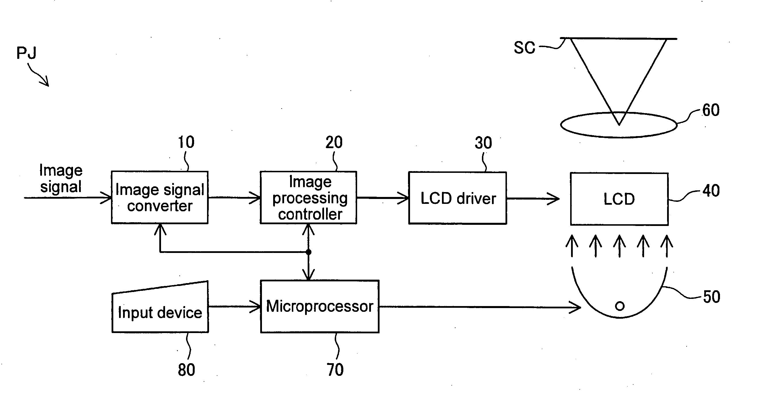
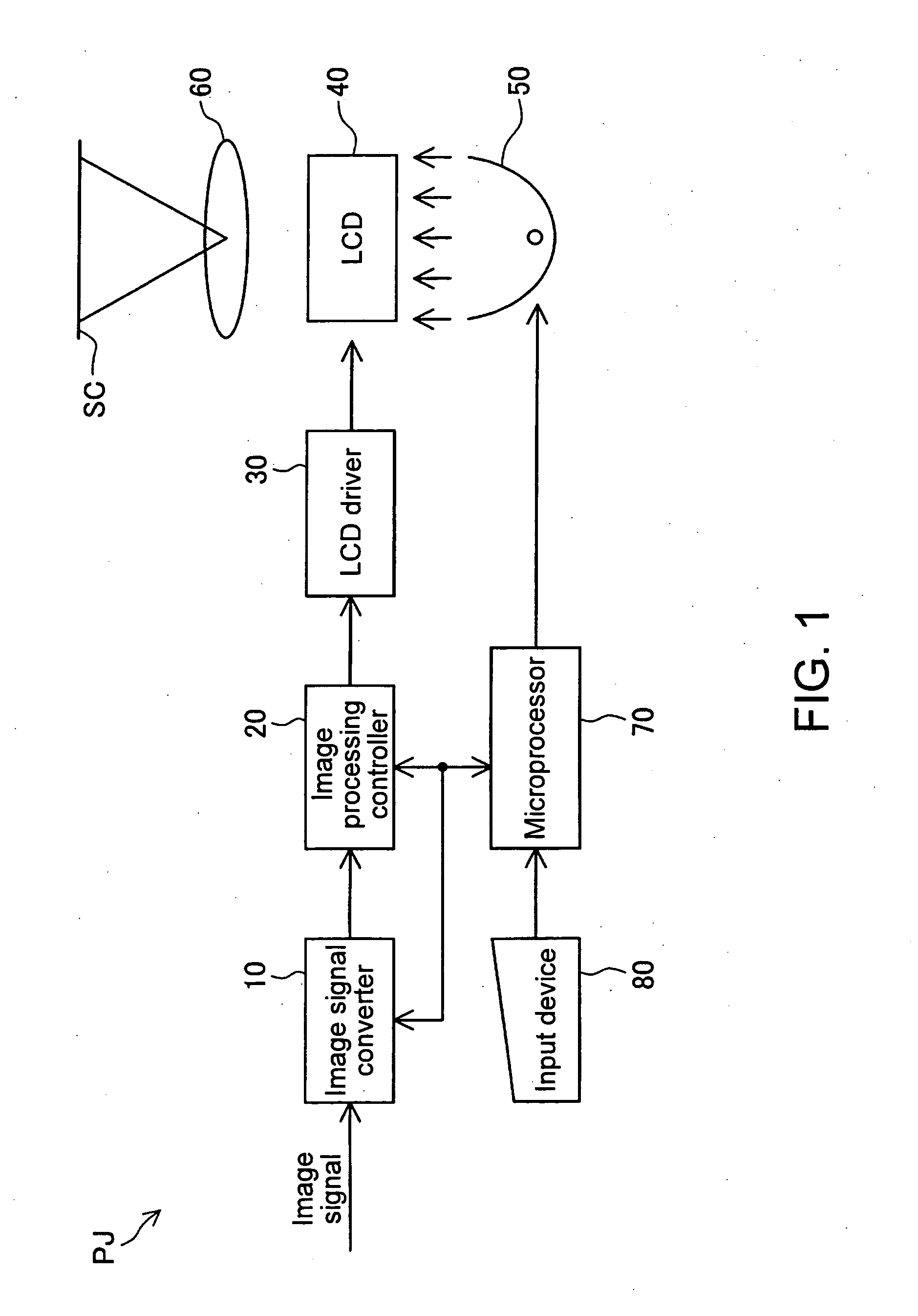
[0039]FIG. 1 is an exemplary block diagram showing the whole configuration of a projector according to the invention. As shown in FIG. 1, a projector PJ can include an image signal converter 10, an image processing controller 20, a liquid crystal display panel (LCD) driver 30, a liquid crystal display panel (LCD) 40, an illuminating optical system 50, a projection optical system 60, a microprocessor 70, and an input device 80.

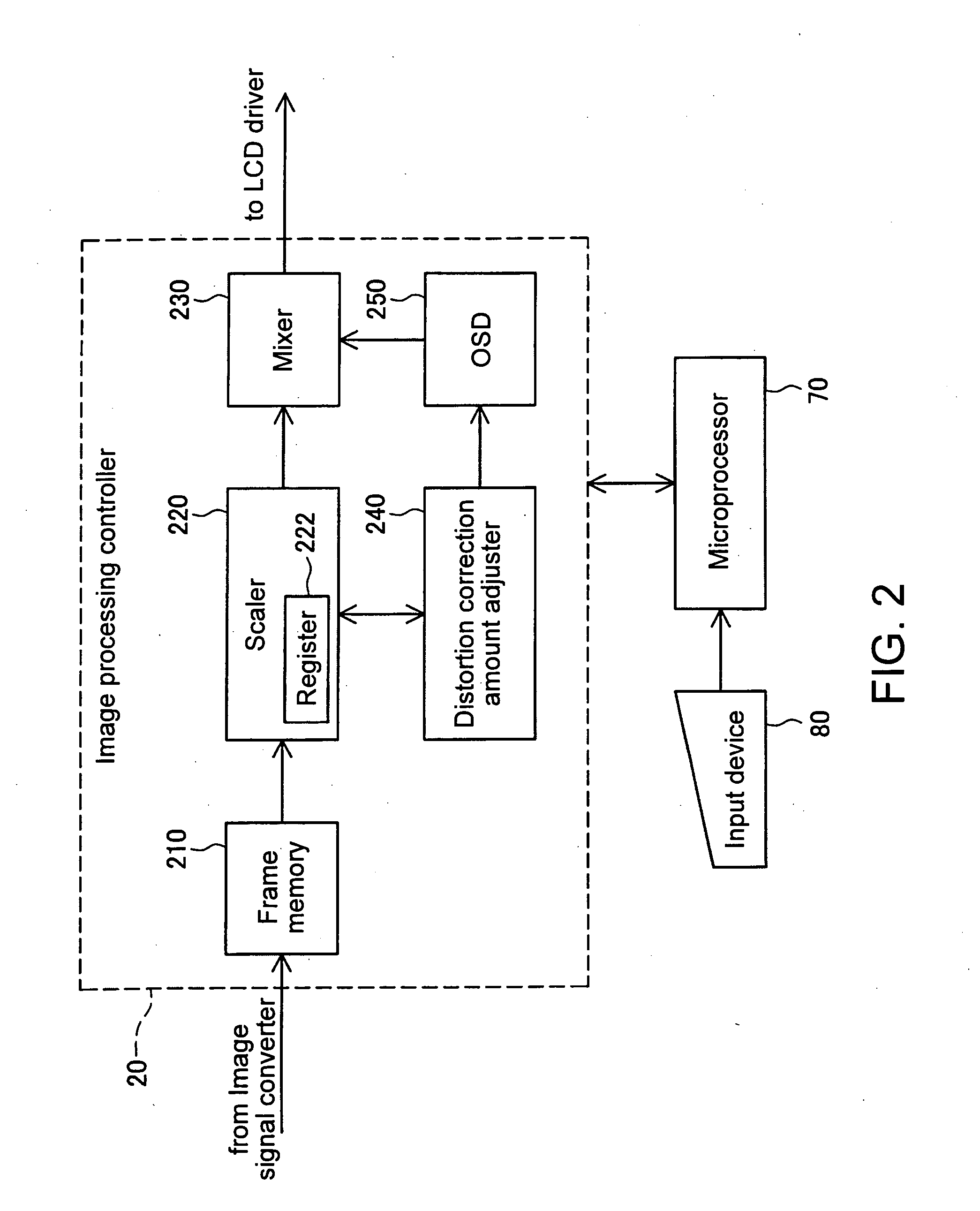
[0040]FIG. 2 is an exemplary block diagram showing the configuration of the image processing controller 20 shown in FIG. 1. The image processing controller 20 includes a frame memory 210, a scaler 220, an onscreen display part (OSD) 250, a mixer 230, and a distortion correction amount adjuster 240 as shown in FIG. 2.

[0041] The operation of image projection, which is a normal operation of the projector PJ, will now be described. Referring to FIG. 1, when a user sends a command to start image projection using the input device 80, the command is sent to the micr...


PUM


Abstract

An exemplary aspect of the invention can provide a method for easily adjusting the distortion of a projected image. In adjusting the amount of distortion correction, values of the amount of distortion correction for a desired outline form to be formed based on desired positions are calculated after the desired positions can be specified. Then whether all the calculated values of the amount of distortion correction are within a predetermined range where an original image is transformable into a distortion correction image can be judged. If all the calculated values of the amount of distortion correction are within the predetermined range, the calculated values of the amount of distortion correction can be set in an image distortion correction part. If a value out of the calculated values of the amount of distortion correction is beyond the predetermined range, outlines corresponding to at least part of the outline form of the projected image are produced, instead of setting the calculated values of the amount of distortion correction in the image distortion correction part. An outline corresponding to the amount of distortion correction beyond the predetermined range can be made differently from an outline corresponding to the amount of distortion correction within the predetermined range, so that each is identified.

Description

BACKGROUND OF THE INVENTION [0001] 1. Field of Invention [0002] The present invention relates to a method for correcting projected image distortion that occurs when an image is projected by a projector obliquely on a projection surface. [0003] 2. Description of Related Art [0004] In a projector, light emitted from an illumination optical system is modulated by a spatial light modulator, such as a liquid crystal light valve (liquid crystal panel) according to an image signal. The modulated light is projected on a projection surface, and thus an image is displayed. Examples of spatial light modulators may include, but not be limited to the crystal light valve. For example, a projector may employ Digital Micromirror Device™ (a trademark of Texas Instruments Incorporated) or devices using other technologies. [0005] When an image is projected on a projection surface with the central axis of light for forming an image (image light) emitted from a projector not corresponding to the normal ...

Claims


Application Information

Patent Timeline
IPC IPC(8): G02F1/133G03B21/00H04N5/74
CPCH04N9/3185H04N5/74
Inventor KUBO, TAKEHIROTOKUYAMA, TETSURO
Owner SEIKO EPSON CORP
Why Eureka
Try Eureka