
Particle detection system

a particle detection and particle technology, applied in particle and sedimentation analysis, measurement devices, instruments, etc., to achieve the effect of accurate particle size determination and increased submicron particle detection sensitivity

Inactive Publication Date: 2005-02-03
DEFREEZ RICHARD K +2
View PDF12 Cites 18 Cited by
  • Summary
  • Abstract
  • Description
  • Claims
  • Application Information

AI Technical Summary

Benefits of technology

[0006] An object of the invention is, therefore, to provide a particle detection method and system characterized by increased submicron particle detection sensitivity and accurate particle size determination.
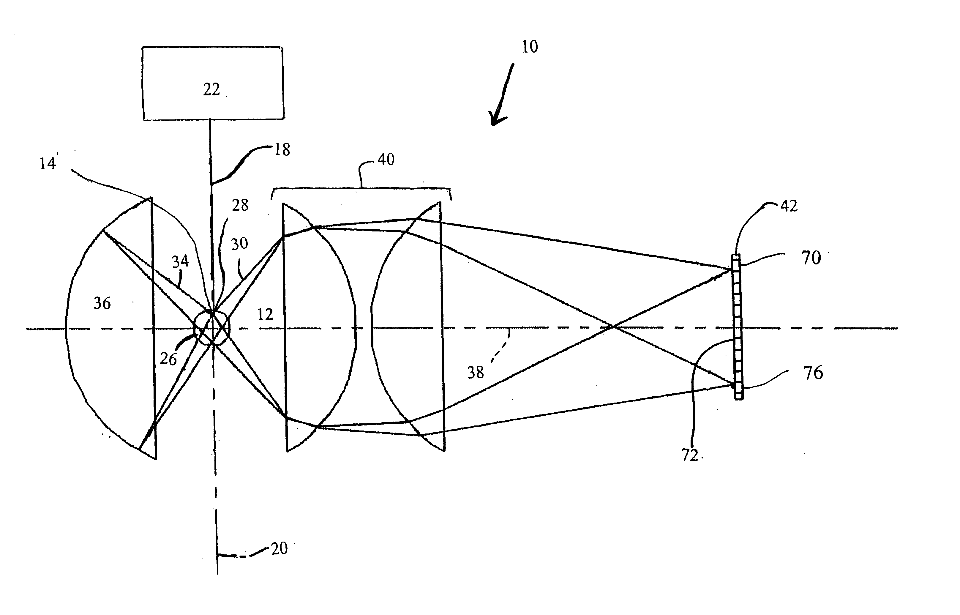
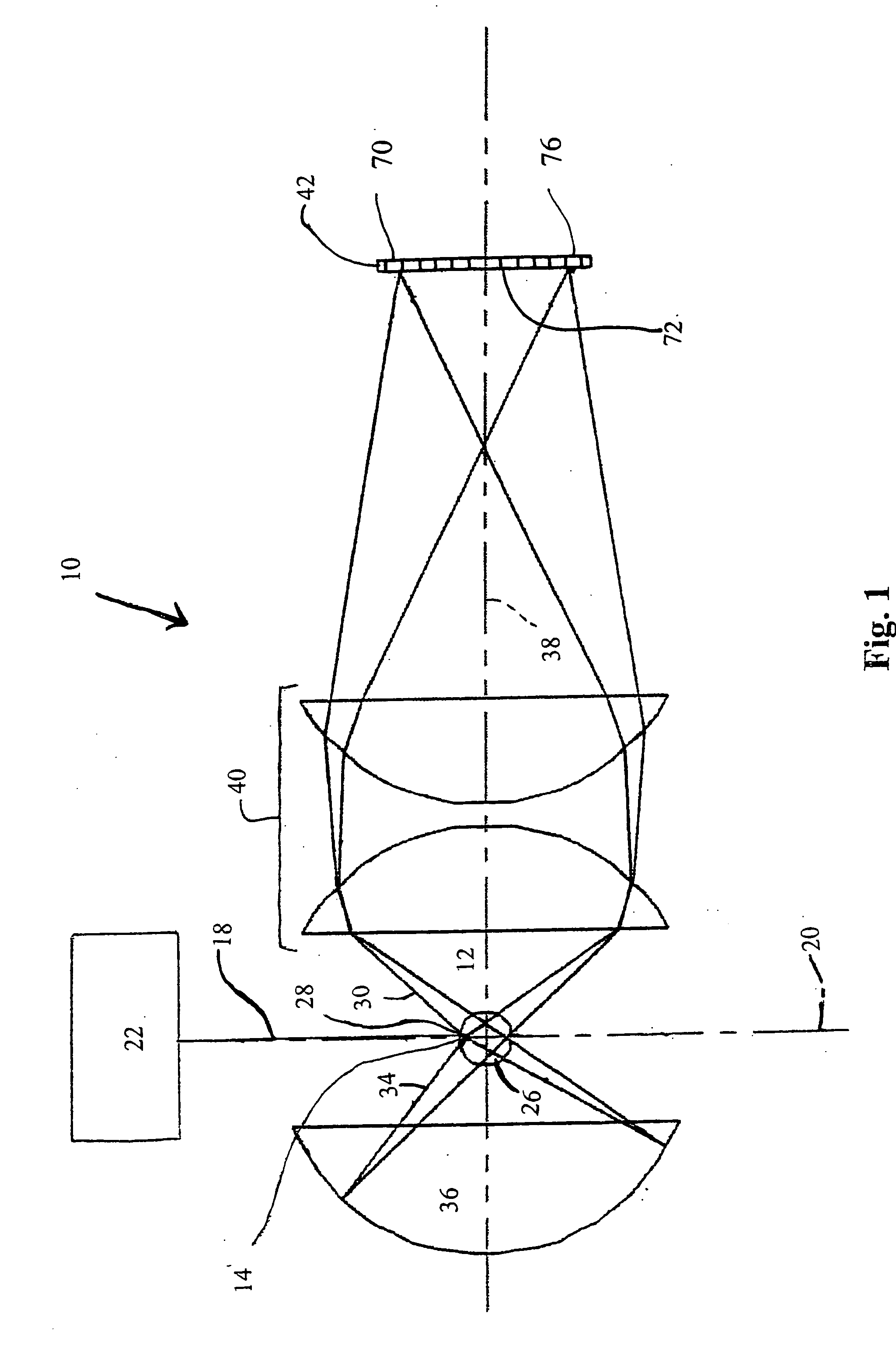
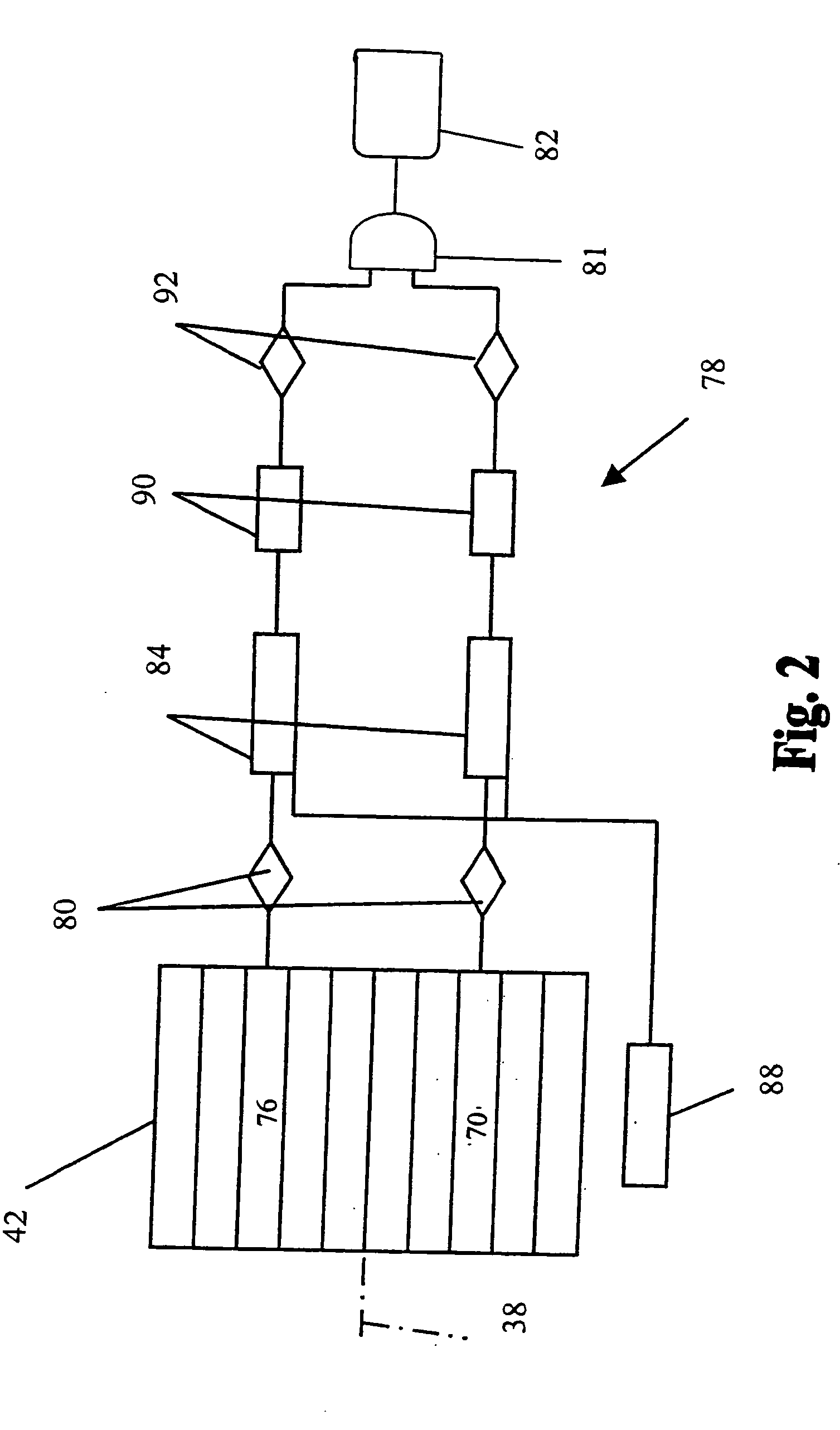
[0009] Signal enhancement results from the required temporal and spatial coincidence of pulse output signals corresponding to the same sample particle. Because sample particles are counted only when both detector elements of a pair concurrently detect a scattered light component and when the resultant pulse output signals exceed a predetermined threshold, randomly occurring noise pulses or excursions are unlikely to concurrently contact both of the detector elements in the pair. Specifically, the probability that two pulse output signals will concurrently exceed the predetermined threshold is equal to the square of the probability that an individual pulse output signal will exceed the threshold. The coincidence function permits the use of a lower threshold for a given false count rate because most noise is random and will not concurrently trigger both detector elements in the pair. Use of a lower threshold facilitates the detection of smaller sample particles.
[0011] The particle detection system of the present invention has an increased ability to distinguish between noise and low-amplitude pulse output signals caused by small diameter particles. The required temporal and spatial coincidence of pulse output signals results in signal enhancement. Because sample particles are counted only when both symmetrically opposed detector elements concurrently detect scattered light correlated components having a pulse output signal that exceeds a predetermined threshold, the incidence of randomly occurring noise pulses or excursions causing a false signal is significantly decreased. Specifically, the probability that two pulse output signals will concurrently exceed the predetermined threshold is equal to the square of the probability that an individual pulse output signal will exceed the threshold. Consequently the threshold for a given false count rate may be lowered by more than a factor of the square root of two while maintaining the desired overall false count rate. Thus the coincidence function allows the use of a lower threshold setting without increasing the incidence of false particle signals, since most noise is random and is unlikely to concurrently trigger both detector elements of a symmetrically opposed pair. The use of a lower threshold facilitates more accurate detection of smaller diameter particles.

Problems solved by technology

As integrated circuits become more compact, line widths decrease, thus reducing the size of particles that can cause quality problems.

Method used


Image

  • Particle detection system
  • Particle detection system
  • Particle detection system

Examples


Embodiment Construction

[0018] The particle detection system of the present invention has an increased ability to distinguish between noise and pulse output signals generated by small particles incident upon a light beam. This increased ability results from the incorporation of a light reflector, a pair of detector elements that detect correlated portions of a light beam scattered in multiple directions by a particle, and a coincidence circuit that determines whether the detector elements in the pair concurrently generate pulse output signals exceeding a predetermined threshold. If both detector elements of the pair concurrently generate pulse output signals, there is a high probability that the signals were caused by the incidence of a sample particle on the light beam rather than by noise variations in the particle detection system. The ability of the particle detection system of the present invention to distinguish low-amplitude pulse output signals from noise enables the system to detect smaller diamet...


PUM

PropertyMeasurementUnit
distancesaaaaaaaaaa
volumeaaaaaaaaaa
thresholdaaaaaaaaaa

Abstract

A particle detection system exhibits an increased ability to detect the presence of submicron diameter particles and to distinguish between noise and pulse output signals generated by small diameter particles on which a light beam is incident. This increased ability results from the incorporation of a light reflector, a pair of detector elements that detect correlated portions of the light beam that have been scattered in multiple directions, and a coincidence circuit that determines whether each detector element in the pair concurrently generates a pulse output signal exceeding a predetermined threshold. Sample particles are counted only when both detector elements concurrently detect scattered light components.

Description

RELATED APPLICATIONS [0001] This application is a division of U.S. patent application Ser. No. 10 / 407,650, filed Apr. 4, 2003.TECHNICAL FIELD [0002] The present invention relates to optical particle detection and, in particular, to a particle detection system with increased sensitivity in the detection of submicron diameter particles. BACKGROUND OF THE INVENTION [0003] Contamination control, including particle monitoring, plays a critical role in the manufacturing processes of several industries. These industries require clean rooms or clean zones with active air filtration and require the supply of clean raw materials such as process gases, deionized water, chemicals, and substrates. In the pharmaceutical industry, the Food and Drug Administration requires particle monitoring because of the correlation between detected particles in an aseptic environment and viable particles that contaminate the product being produced. Semiconductor fabrication companies require particle monitoring...

Claims


Application Information

Patent Timeline
Patent Type & Authority Applications(United States)
IPC IPC(8): G01N15/14G01N21/53
CPCG01N15/1429G01N2015/1402G01N21/53G01N15/1459
Inventor DEFREEZ, RICHARD K.BRADY, JAMESGIRVIN, KENNETH L.
Owner DEFREEZ RICHARD K
Learn More