Position adjustment apparatus, optical pickup apparatus and position adjustment method

a technology of optical pickup and position adjustment, which is applied in the direction of disposition/mounting of heads, instruments, optical beam sources, etc., can solve the problems of not always in the ideal position in terms of design, complicated adjustment equipment, and time and labor, etc., to facilitate the position adjustment of an optical axis and simplify the structure of the apparatus

Inactive Publication Date: 2005-02-03
SHARP KK
View PDF11 Cites 9 Cited by
  • Summary
  • Abstract
  • Description
  • Claims
  • Application Information

AI Technical Summary

Benefits of technology

[0012] It is an object of the invention to provide a position adjustment apparatus, an optical pickup apparatus, and a position adjustment method which can simplify structures of the apparatuses and facilitate position adjustment of an optical axis.

Problems solved by technology

Therefore, in the respective related arts, adjustment work and a constitution of the apparatus are complicated, which also makes adjustment equipment complicated.
This requires time and labor.
However, the light-emitting portions 2a and 11a are not always in ideal positions in terms of design depending upon component accuracy and the like.
Therefore, in addition to the complicated adjustment work, the number of components increases, which causes. an increase in costs.

Method used


Image

  • Position adjustment apparatus, optical pickup apparatus and position adjustment method
  • Position adjustment apparatus, optical pickup apparatus and position adjustment method
  • Position adjustment apparatus, optical pickup apparatus and position adjustment method

Examples


Embodiment Construction

[0102] Now referring to the drawings, preferred embodiments of the invention are described below.

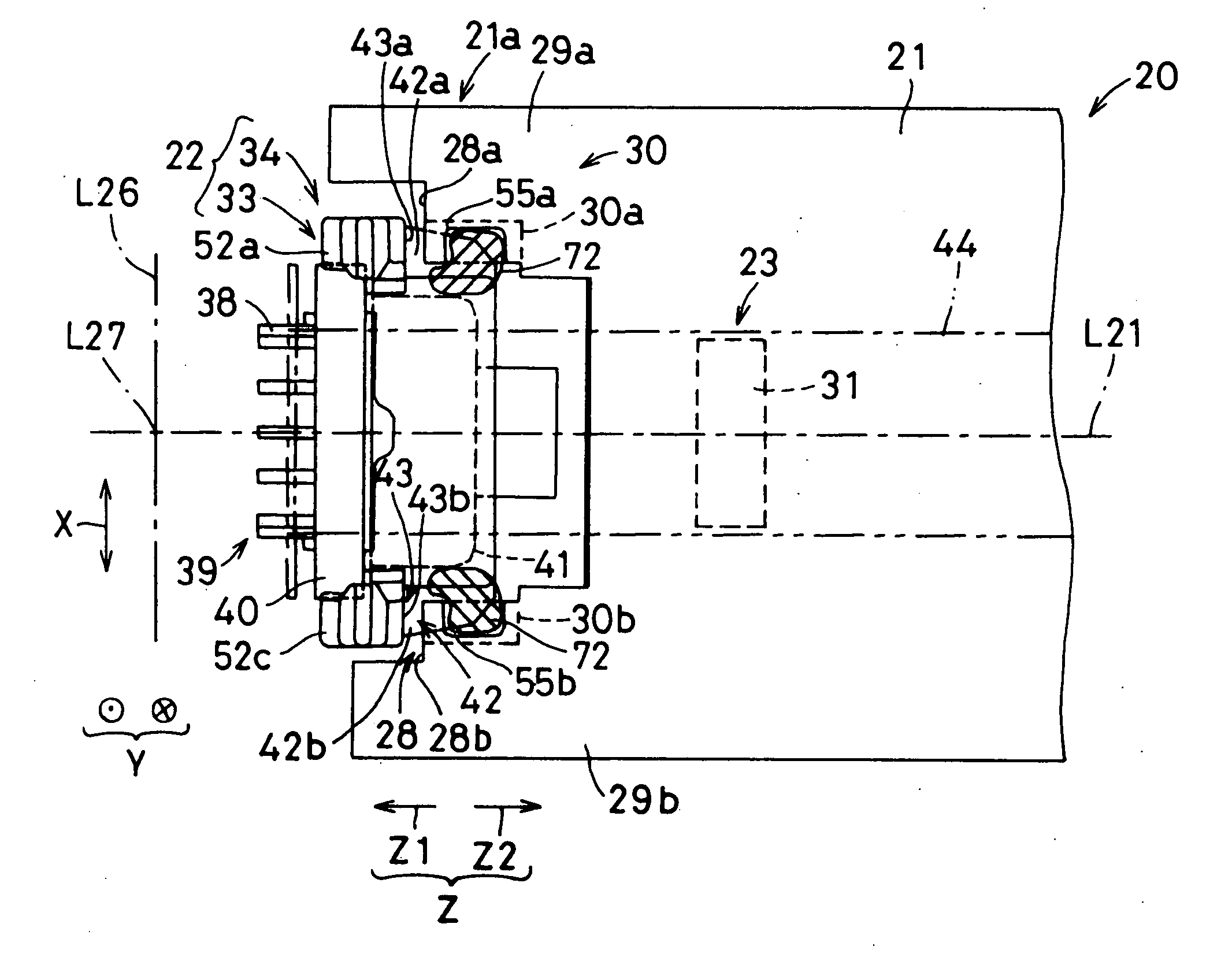
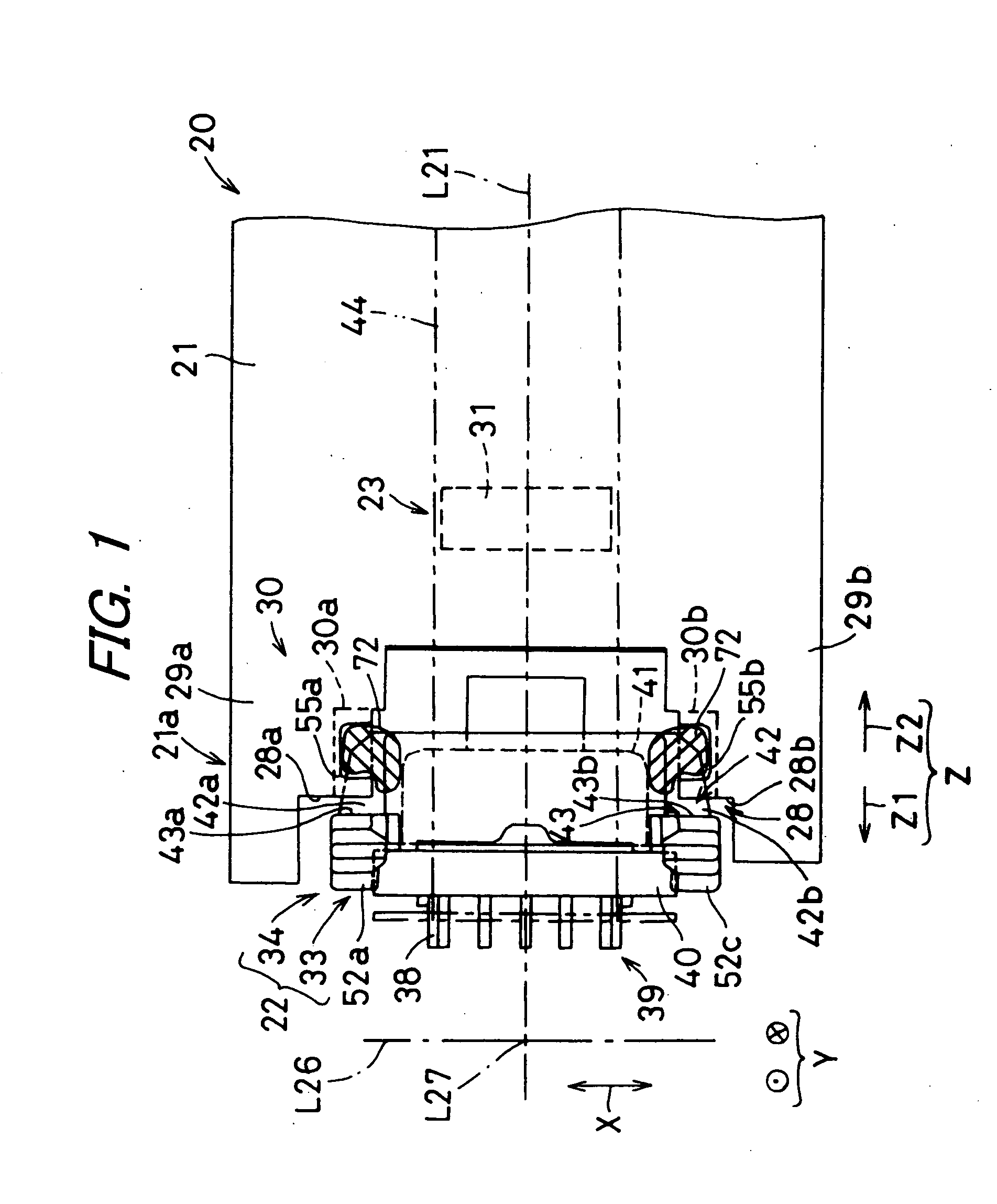
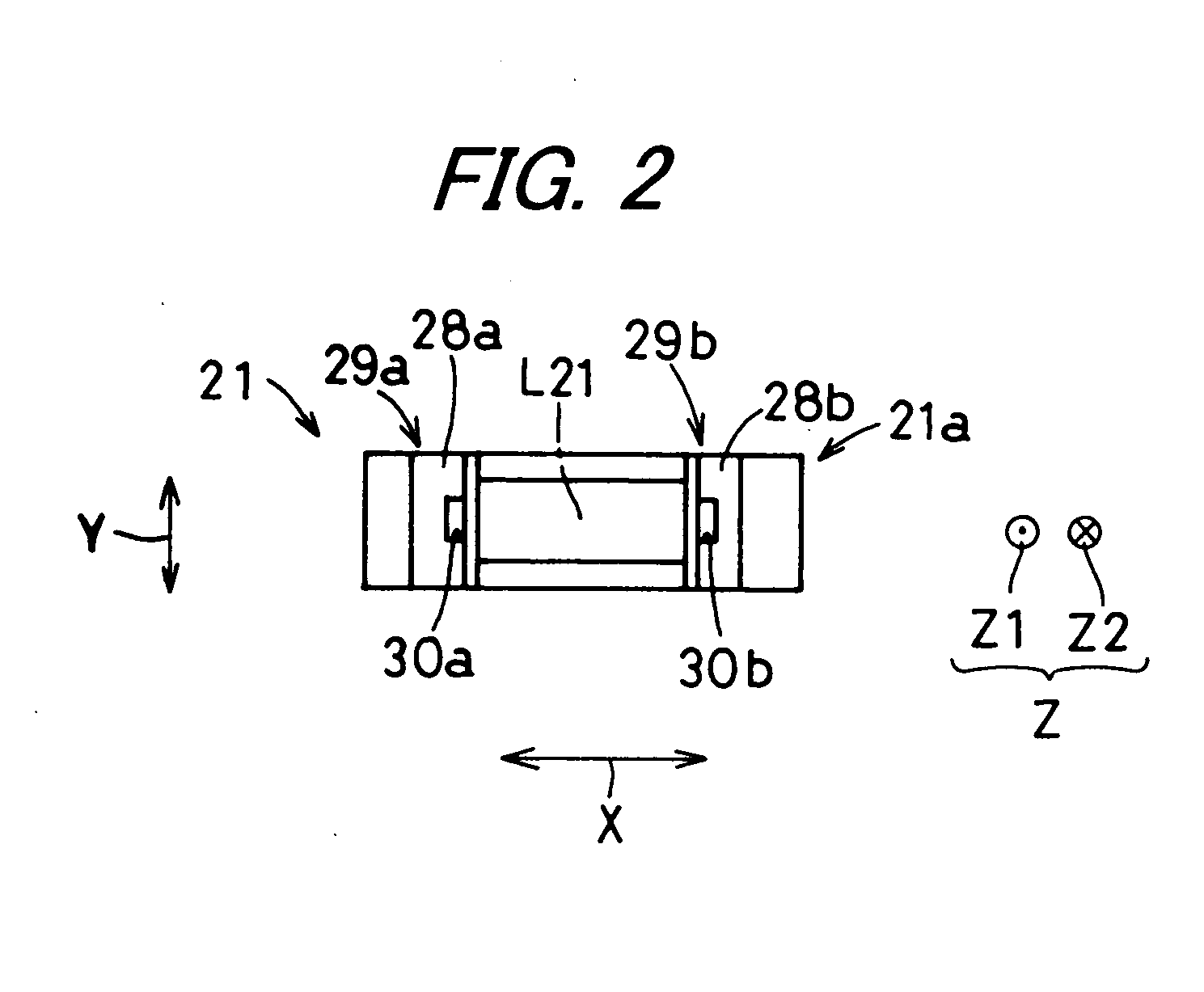
[0103]FIG. 1 is a front view showing a part of an optical pickup apparatus 20 according to an embodiment of the invention. FIG. 2 is a plan view showing one side portion 21a of a housing 21. The optical pickup apparatus 20 is an apparatus for recording or reproducing information by irradiating a recording medium (not shown) such as a Compact Disk (CD) with light. The optical pickup apparatus 20 includes a housing 21 and a light source unit 22. An operator adjusts a position of the light source unit 22 with respect to the housing 21 in accordance with a work procedure based upon a position adjustment method for the light source unit 22 of the invention using a position adjustment apparatus 60 for the light source unit 22 of the invention.

[0104] The light source unit 22 is provided in one side portion 21a of the housing 21. The one side portion 21a of the housing 21 is formed in a recess...


PUM

PropertyMeasurementUnit
viscosityaaaaaaaaaa
viscosityaaaaaaaaaa
temperatureaaaaaaaaaa

Abstract

A chuck portion provided to keep a fixed positional relation with respect to a housing, holds a light source unit detachably. This chuck portion is displaced from an advanced position to a retracted position to displace the light source unit which is in a provisional position with respect to the housing, in a direction being away from the housing along a reference axis and the light source unit is retracted from the housing. In a state where the light source unit which is in this position is held by the chuck portion, the light source unit is slid and displaced in a direction crossing the reference axis with respect to the housing, angularly displaced about the reference axis and an axis crossing the reference axis, and then fixed to the housing.

Description

BACKGROUND OF THE INVENTION [0001] 1. Field of the Invention [0002] The present invention relates to an optical pickup apparatus which includes a light source unit and irradiates light from the light source unit on a recording medium to thereby record or reproduce information, and a position adjustment apparatus and a position adjustment method for adjusting a position of the light source unit. [0003] 2. Description of the Related Art [0004]FIG. 32 is a sectional view showing an optical pickup apparatus 1 in one related art. In one related art, for example, disclosed in the Japanese Unexamined Patent Publication JP-A 2002-342945, a laser beam from a semiconductor laser 2 is guided to an objective lens 4 via a collimator lens 3 opposed to the semiconductor lens 2. The semiconductor lens 2 is held by a laser holder 5, and a spherical seat 6 is interposed between this laser holder 5 and a housing 7. [0005] The laser holder 5 and the spherical seat 6 are brought into abutment against ea...

Claims


Application Information

Patent Timeline
Patent Type & Authority Applications(United States)
IPC IPC(8): G11B7/08B23P19/00G01B11/02G11B7/125G11B7/22
CPCY10T29/53178G11B7/22
Inventor NAKAMURA, MASAHIROYOSHIZAWA, AKIHOHATAZAWA, KENJI
Owner SHARP KK
Why Eureka
Try Eureka