
Wireless local area network translating bi-directional packet repeater

a bi-directional packet repeater and wireless network technology, applied in transmission monitoring, frequency-division multiplex, dc level restoring means or bias distortion correction, etc., can solve the limitations of the range of communication between wireless devices, the installation of wiring, and the use of devices that can greatly affect the usable range, so as to reduce the available bandwidth, extend the range of wireless communication, and enable communication

Active Publication Date: 2005-02-03
MICROSOFT TECH LICENSING LLC
View PDF4 Cites 33 Cited by
  • Summary
  • Abstract
  • Description
  • Claims
  • Application Information

AI Technical Summary

Benefits of technology

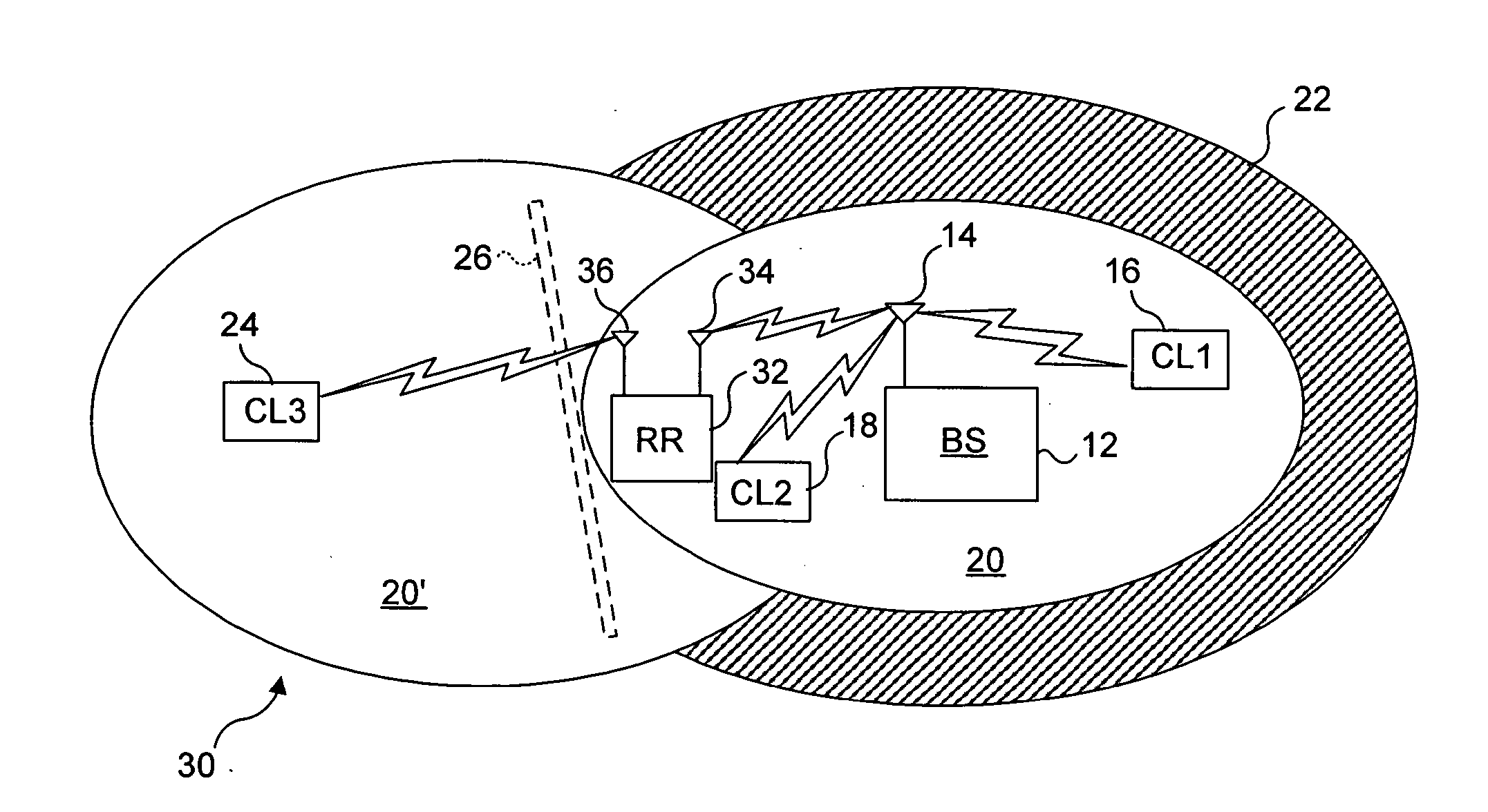
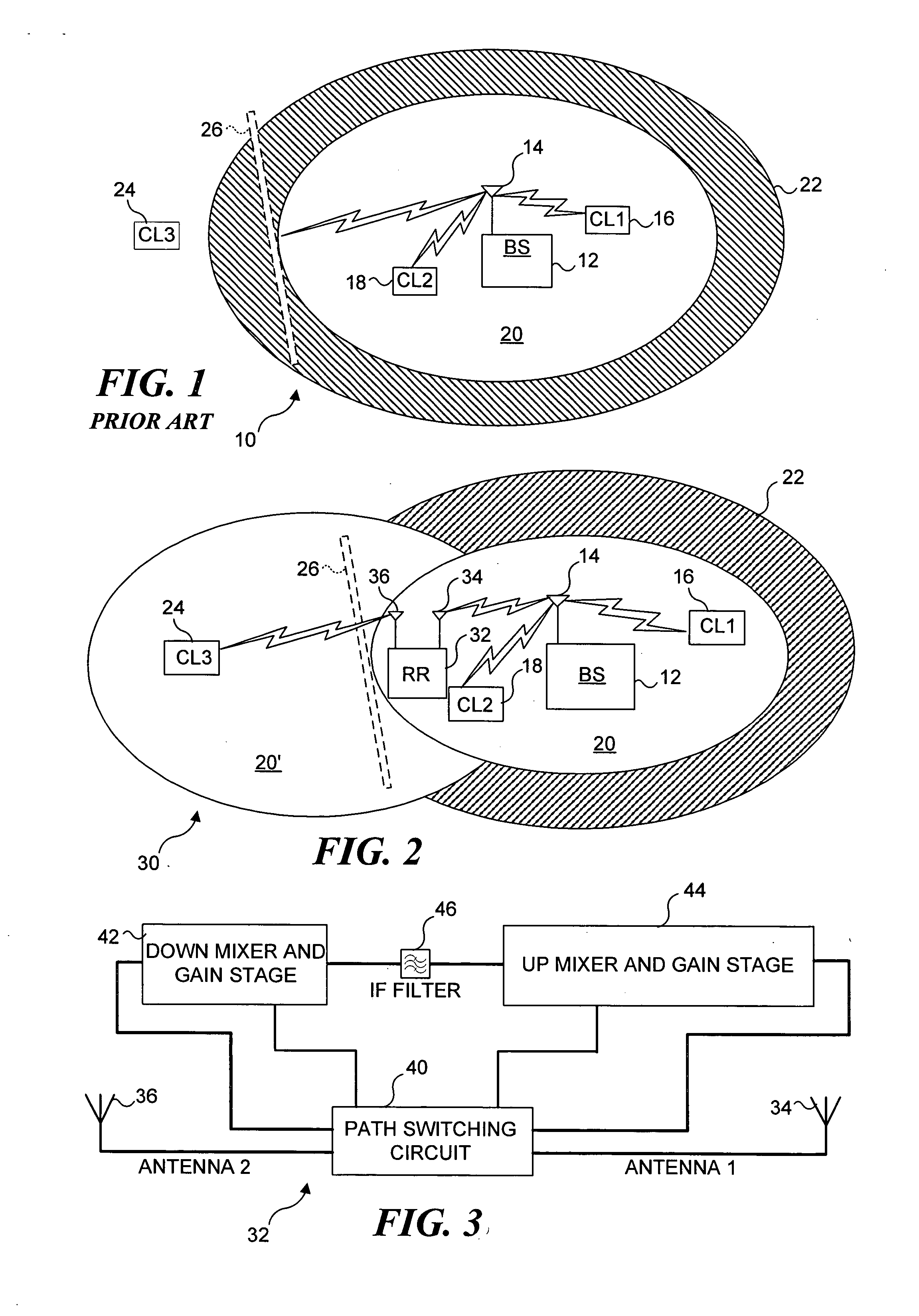
[0008] The present invention extends the range of wireless communication between wireless devices. The present invention is also useful in enabling communication between wireless devices when one or more walls or other elements of a structure in which a wireless network is active are disposed between the wireless devices. Use of the present invention does not significantly reduce the available bandwidth or substantially increase the time for communication between wireless devices, because data packets are retransmitted within microseconds of being received and on a different channel, unlike prior art repeaters that receive, buffer, and then repeat the transmission of data packets on the same channel. In the present invention, upon receipt of the data packets by the intended recipient, an acknowledgment is sent to the original source of the data packets, via the translating bi-directional packet repeater of the present invention.
[0015] In a typical application, the first antenna and the second antenna will preferably be directional antennas that have a preferred direction relative to receiving and transmitting wireless signals. Using such antennas, the translating bi-directional packet repeater can better convey wireless signals between wireless devices disposed at two disparate locations without cross interference, and can retransmit wireless signals so that they are directed around intervening structural elements, such as walls.

Problems solved by technology

Most people would prefer to avoid installing the wiring that would be required for a conventional Ethernet network, due to the expense and difficulty.
However, there are clearly limits in the range of communication between wireless devices, regardless of the version of the 802.11 specification that is applicable.
The environment in which wireless devices are used can greatly affect their usable range.
For example, when brick and stone, or metal framing are employed for interior walls in the construction of homes and other buildings in which wireless devices are used, these structures substantially attenuate the wireless signals, greatly reducing the effective distance for wireless communications between wireless devices.
Consequently, it may be impossible to achieve reliable wireless communications between an access point at one point in a structure and another wireless device located at a disparate point in the structure.
However, the installation of additional access points requires adding wiring, which is contrary to the purpose of using a wireless network.
However, such repeaters are analog device and are typically not bi-directional, since they are designed to receive a signal from a commercial transmitter and repeat the transmission of the signal on another frequency to the receivers (radio or television) in a more distant location.
Also, these unidirectional prior art analog repeaters are not usable in a packet network.
Range extending repeaters are available for wireless networks, but they use an excessive amount of the available bandwidth.
When used in repeater mode, this device substantially increases the demand on the available bandwidth, because it must receive packets from an access point or base station, store the packets, and then retransmit the packets to the intended recipient—on the same channel.
Also, the manufacturer cautions that this repeater will only work with certain “compatible access points and routers.”
Currently, none of the prior art wireless devices provide such functionality.

Method used


Image

  • Wireless local area network translating bi-directional packet repeater
  • Wireless local area network translating bi-directional packet repeater
  • Wireless local area network translating bi-directional packet repeater

Examples


Embodiment Construction

[0024] Prior Art Wireless Network Showing Problems Addressed by Present Invention

[0025] An example of a relatively simple wireless network 10 is illustrated in FIG. 1. This Figure is labeled as prior art and illustrates the problems addressed by the present invention. In this simple example, a base station 12 includes an antenna 14 that transmits and receives wireless signals to and from a first client 16 and to and from a second client 18, each client comprising a computing device such as a laptop having an appropriate wireless interface. The base station and clients are all disposed within a region 20 corresponding to the range of acceptable wireless communications between these components. While indicated schematically as an oval, the region in which acceptable wireless communications can occur between such devices is typically not as regular. Also, as is well known, wireless communications between wireless devices can often be carried out at reduced data rates as the distance b...


PUM


Abstract

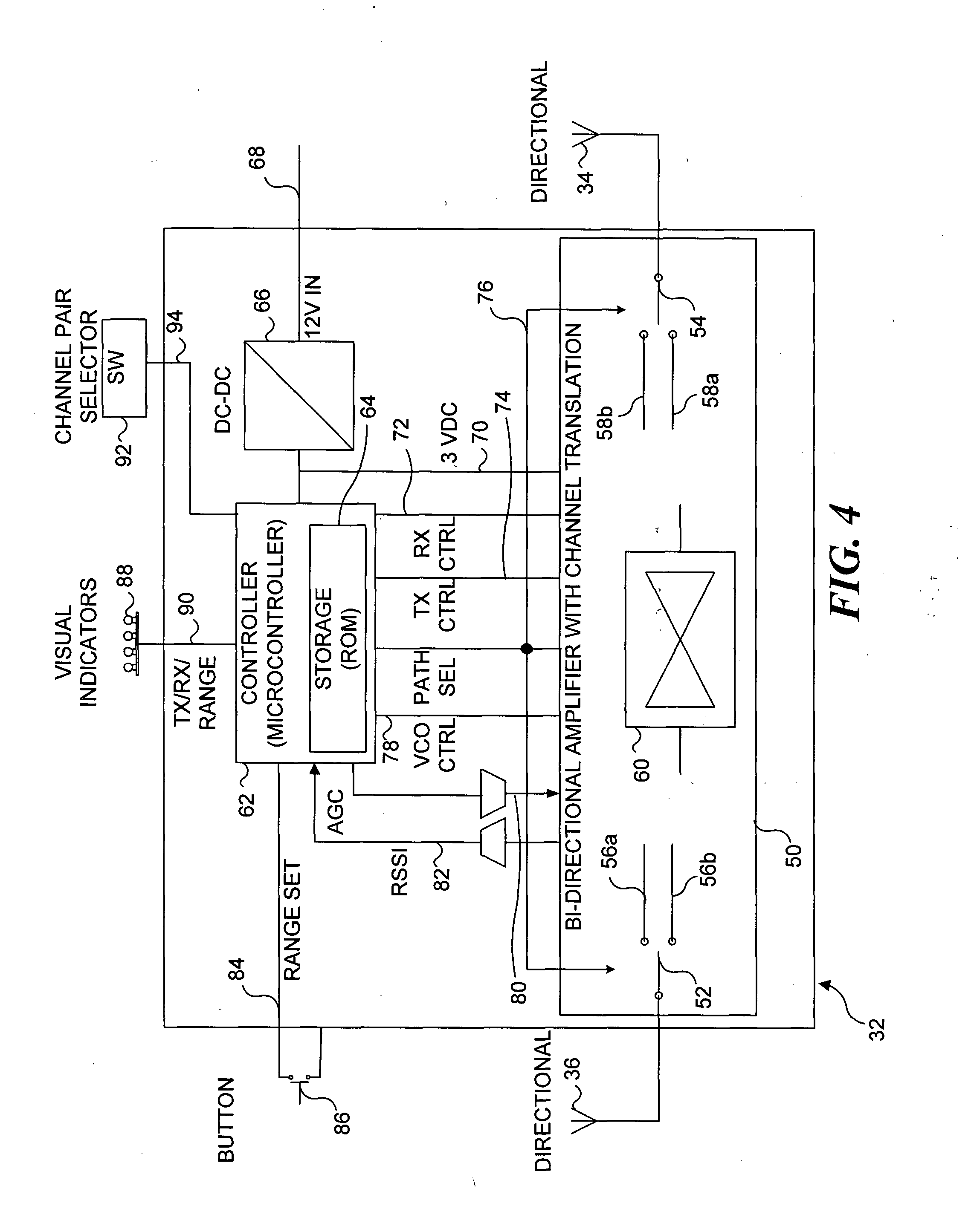
A translating bi-directional packet repeater includes a first antenna and a second antenna for receiving a wireless signal, amplifying it, and retransmitting it on a different channel. The channel associated with each of the antennas is separated in frequency sufficiently to ensure good isolation between the wireless signals that are received and then retransmitted. The wireless signal is down converted to an intermediate frequency (IF) that is passed through a band pass filter, and the filtered signal is then up converted and retransmitted on the different channel. A controller responds to a wireless signal on one of the antennas in selecting a path through the bi-directional amplifier and the antennas used to receive and retransmit the signal. The isolation between the received wireless signal and the retransmitted wireless signal is sufficient to avoid interference, and the retransmission takes place almost instantaneously to minimize the delay incurred.

Description

FIELD OF THE INVENTION [0001] This invention generally pertains to a retransmitter for use in a wireless network, and more specifically pertains to a retransmitter that receives data packets on a first channel of the wireless network and immediately retransmits the data packets on a second channel to extend the range and service of wireless devices communicating on the wireless network. BACKGROUND OF THE INVENTION [0002] There is an increasing demand for wireless networking devices that can be used to connect a plurality of computing devices together in a network. Most people would prefer to avoid installing the wiring that would be required for a conventional Ethernet network, due to the expense and difficulty. Newer wireless network standards, such as the 802.11 g amendment to the specification established by the Institute of Electrical and Electronics Engineers (IEEE), will enable faster wireless data communication than the earlier 802.11b amendment to the specification. However,...

Claims


Application Information

Patent Timeline
IPC IPC(8): H03D7/16H04B1/40H04L12/28H04L12/56H04W4/18H04W16/14H04W16/26
CPCH03D7/161H04B1/40H04B7/15535H04W16/26H04W4/18H04W16/14H04B7/15542
Inventor KING, WAYNE G.
Owner MICROSOFT TECH LICENSING LLC
Learn More