
Spread-spectrum transceiver

Inactive Publication Date: 2005-02-03
UNWIRED BROADBAND INC
View PDF44 Cites 14 Cited by
  • Summary
  • Abstract
  • Description
  • Claims
  • Application Information

AI Technical Summary

Benefits of technology

It is another object of the present invention to provide a spread-spectrum technique for use in a multi-node digital communication network, which can readily incorporate standard error-control coding (whose parameters are matched to the particular application) into the transmission and reception of digital signals propagated by the network.
It is also an object of the present invention to provide a technique whereby conventional equipment designed for generating arbitrary spreading-code sequences can be adapted to the task of generating a family of spreading-code sequences for use in a multi-node digital communication network.
It is a further object of the present invention to provide a technique whereby direct-sequence spectrum spreading, or a hybrid combination of direct-sequence and frequency-hopped spectrum spreading, can be utilized in conjunction with code diversity or “code hopping” in a spread-spectrum digital communication network designed to have a low probability of intercept (LPI).

Problems solved by technology

However, this technique of switching between two independent signals did not achieve widespread acceptance, mainly because it required approximately twice the electronic circuitry of a polarity-inversion technique without providing any better performance.
However, the frequency diversity provided by “hopping” of the carrier readily enables rejection of unintended signals, thereby making the choice of a particular spreading-code sequence relatively unimportant.
Consequently, there has been substantially no research in the prior art on the use of Gold codes and other composite codes for hybrid frequency-hopped and direct-sequence spread-spectrum communication networks.
The use of composite codes (e.g., Gold codes or symmetric codes) for spectrum spreading in such applications has not heretofore been deemed appropriate, because composite codes would require significantly greater hardware complexity to implement than MLLRSs without seeming to provide sufficient compensating advantages over MLLRSs in terms of processing gain, the number of nodes that can be accommodated, the rate of data transmission, or robustness.

Method used


Image

  • Spread-spectrum transceiver
  • Spread-spectrum transceiver
  • Spread-spectrum transceiver

Examples


embodiment i

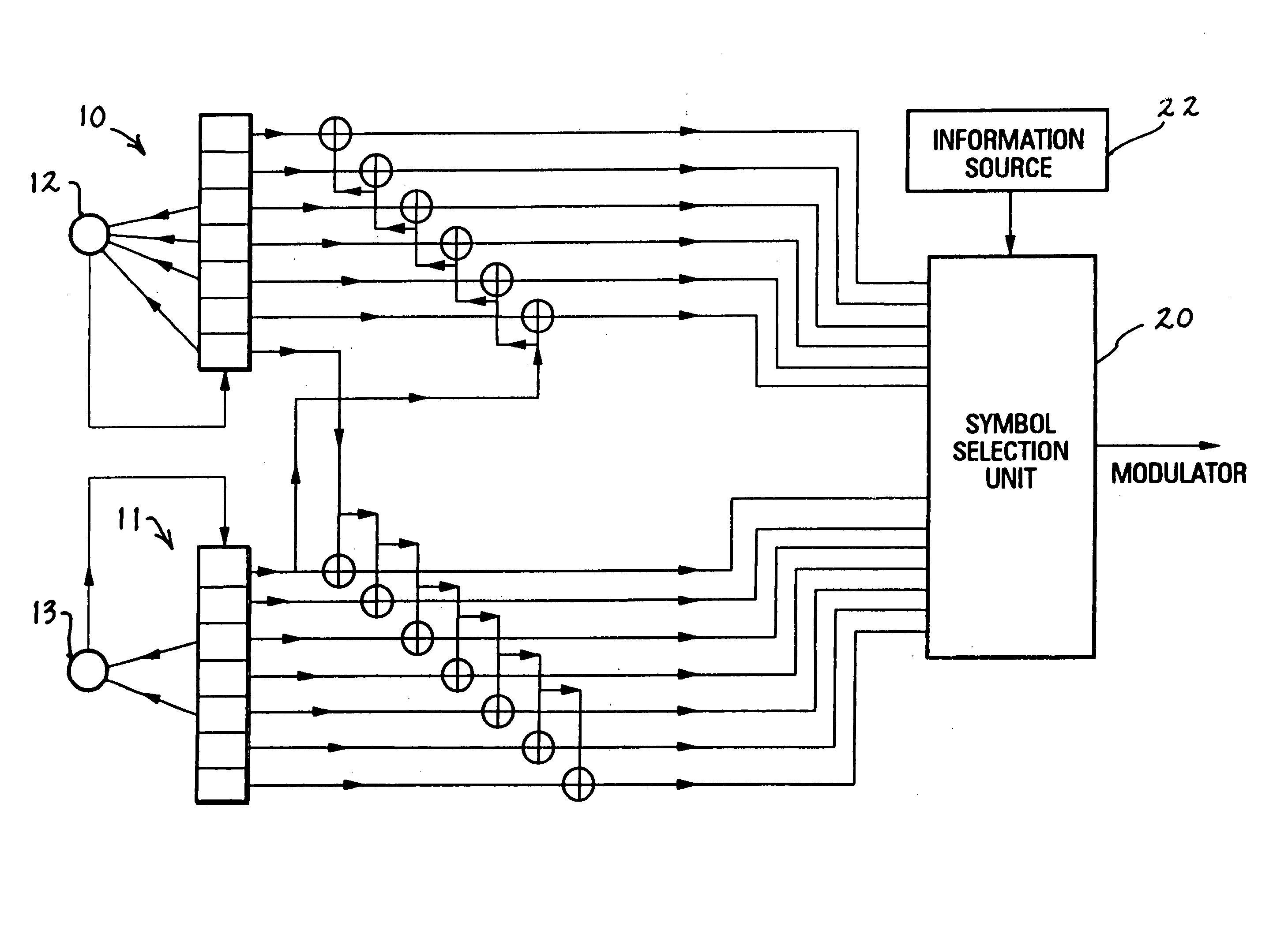
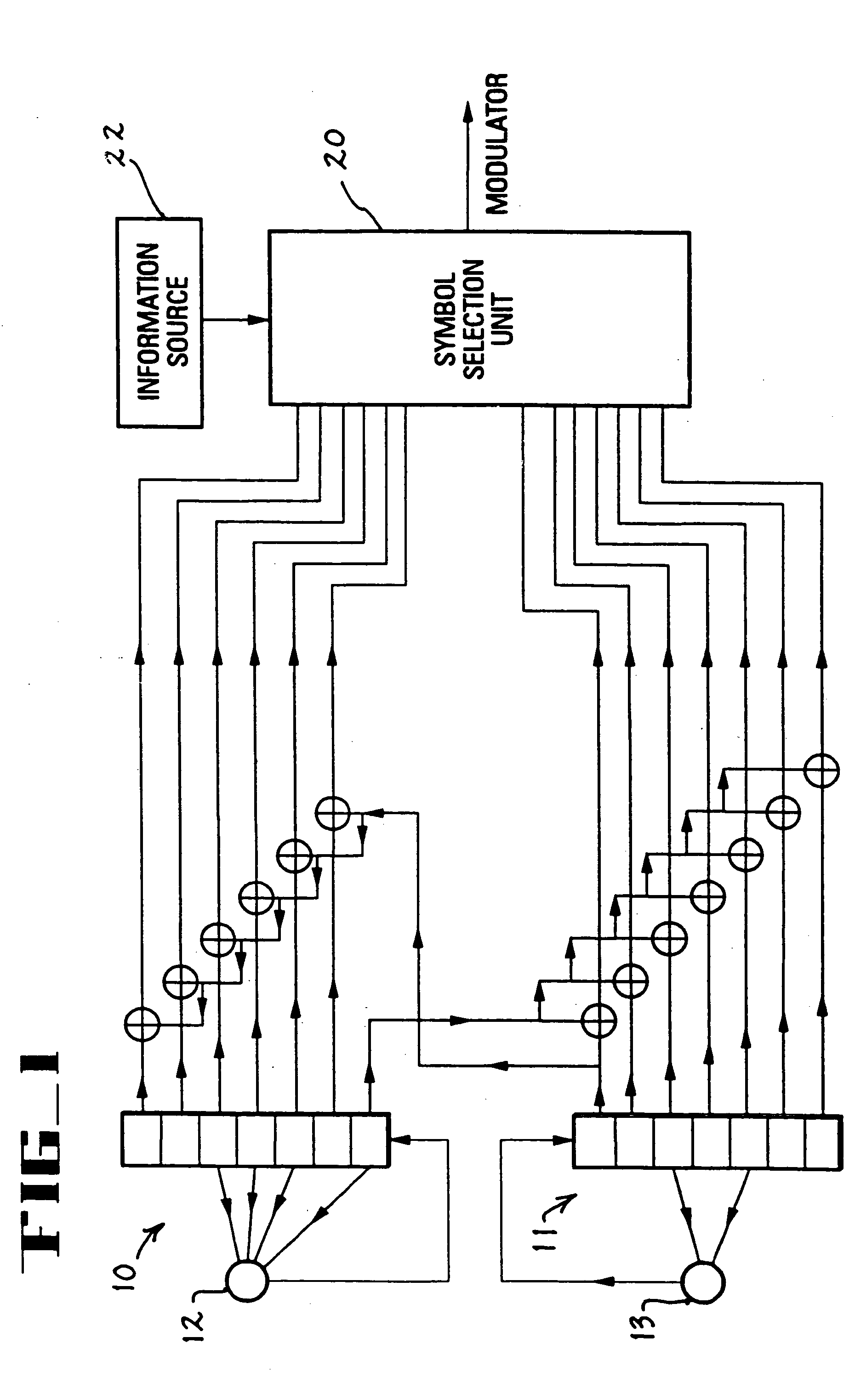
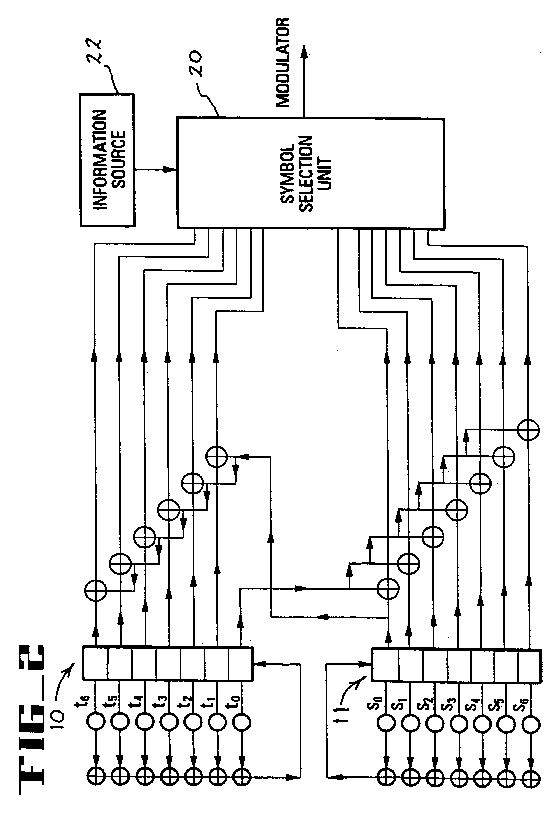
In a particular embodiment of a multi-node digital communication network according to the present invention as illustrated in FIG. 1, a composite code sequence (e.g., a Gold code sequence, a symmetric sequence, a Kasami code sequence, or the like) is used as the spreading-code sequence, and one sequence at a time is transmitted. The number K of spreading-code sequences assigned to each node of the network is 2r, where r is a positive integer such that

1≦r≦[log2 (M1+M2−1)],

where [log2 (M1+M2−1)] denotes the “greatest integer” function, where M1 and M2 represent the numbers of stages in corresponding registers of the two-register spreading-code sequence generator. In the following discussion, it is assumed that M1=M2=M. Modification of the discussion to accommodate a situation in which the registers have different “lengths” (i.e., different numbers of stages) is straightforward.

A spread-spectrum digital communication system according to the present invention can be constructed for ...

embodiment ii

In an alternative embodiment of the present invention, as illustrated in FIG. 5, two spreading-code sequences are selected from among all the available spreading-code sequences generated by the shift registers 10 and 11 during each period of the sequences. The selected sequences are used to modulate the “in-phase” arm and / or the “quadrature” arm, (also called the I-arm and the Q-arm), respectively, of a sinusoidal carrier. Modulation of the I-arm and the Q-arm can be achieved using a quaternary phase-shift keyed (QPSK) modulation, an offset QPSK (also called an OQPSK) modulation, a quadrature partial response (QPR) modulation, or any other type of quadrature modulation. If K spreading-code sequences are available to each node of the network, there are K⁡(K-1)2

possible pairs of spreading-code sequences that can be transmitted per symbol interval. Thus, by selecting two of the K available spreading-code sequences for transmission during each symbol interval, [log2⁢K⁡(K-1)2]

bits o...

embodiment iii

In a third embodiment of the present invention as illustrated in FIG. 6, two spreading-code sequences are selected during each symbol interval, viz., one “upper” sequence and one “lower” sequence from each of the shift registers 10 and 11. If the number of spreading-code sequences available to each node of the network is K=2r, each subset contains 2r−1 sequences, so that 2(r−1) bits of information can be transmitted per symbol interval. If the polarity of each spreading-code sequence is selectively inverted, or not, according to a differential coding scheme, then 2+[2(r−1)]=2r information bits per symbol interval are transmitted. For example, if K=8, then six information bits per symbol are transmitted.

Since symbol decisions are made within each subset of spreading-code sequences, there is no need to choose the “correct” subset in order to identify the “correct” spreading-code sequence. Thus, decision logic is considerably simplified. Also, symbol decisions are made between seque...


PUM


Abstract

An assembly of simultaneously transmitted electrically generated signals, which contains a subset of binary spreading-code sequences that are members of a larger set of binary spreading-code sequences abailable to a particular node of a multi-node communication network. All sequences in the set of spreading-code sequences available to the particular node of the network can be generated by the same configuration of two linear-feedback binary shift registers, where feedback taps of the two linear-feedback binary sift registers correspond to primitive polynomials of the same degree over GF(2), the field of two elements.

Description

TECHNICAL FIELD This invention relates generally to digital communication systems, and more particularly to a spectrum spreading technique for use in multi-node digital communication systems such as digital networks and digital radios. BACKGROUND OF THE INVENTION Spectrum spreading techniques for use in digital communication networks have been described in many books and papers. A classic publication in this field is Spread Spectrum Communications by M. K. Simon, J. K. Omura, R. A. Scholtz and B. K. Levitt, Computer Science Press, 11 Taft Court, Rockville, Md. 20850, 1985. Particular kinds of spectrum spreading techniques that have been implemented in digital communication networks in the prior art include “direct-sequence spreading”, “frequency hopping”, “time hopping”, and various hybrid methods that involve combinations of the aforementioned techniques. Multi-node spread-spectrum communication networks developed in the prior art were generally characterized as code-division mu...

Claims


Application Information

Patent Timeline
IPC IPC(8): H04B1/707H04B1/7075H04J13/00H04J13/10H04J13/16
CPCH04B1/707H04B1/7075H04J13/00H04J13/16H04J13/0077H04J13/10H04J13/102H04J13/0074
Inventor RICE, BART E.
Owner UNWIRED BROADBAND INC
Learn More