
Systems and methods for software and firmware testing using checkpoint signatures

Inactive Publication Date: 2005-02-03
HEWLETT PACKARD DEV CO LP
View PDF12 Cites 51 Cited by
  • Summary
  • Abstract
  • Description
  • Claims
  • Application Information

AI Technical Summary

Problems solved by technology

However, when testing high-end embedded server firmware, an operating system (OS) may not be running on the system under test.
Once such a computer system has been initialized, the environment may still be very internal to the system, making it very difficult to get data out of the system.
The embedded firmware does not have hardware available for its use.
Therefore, problems arise with getting data about firmware code execution out of the system under test.
In a high-end server firmware test environment these OS administered components are typically not available, especially early in execution of firmware code, before advance initialization.
However, such a device only monitors read only memory (ROM) accesses.
As a further problem a PromICE device is typically unaware of multiple processor (MP) situations.
Therefore, a PromICE device will not function properly when more than one processor has accessed a particular section of code.
Due to PromICE lacking multiprocessor support, PromICE may, as a practical matter, only be used on a per cell basis in multi-nodal computer systems and only on development machines.
As a result any ROM relocation carried out by the firmware would cause an erroneous indication that the PromICE has provided complete coverage, particularly if the PromICE is not set up properly.
Also, instruction caches cause coverage data integrity problems in such a test device.
PromICE may not be used to aid in debugging and root cause analysis as these functions are beyond existing PromICE device capabilities.
Also, no method of ‘pass / fail’ based on coverage statistics is typically provided by such test devices.
Another problem is that as binaries change, as software is changed to fix problems that have been found in previous tests, data from previous tests is not tied together in a meaningful manner.
These devices do provide some information, but the information is so diverse and changes so quickly that it is not very useful.
Again, this existing solution has the same problems as hardware, in that it only captures the results of instruction execution.
Whereas a simulator is typically unable to easily map specific tests to specific coverage reports, test suite targeting typically requires manual manipulation of the simulator.
Another problem with a simulator is that the simulator cannot exactly replicate the actual hardware that it is trying to simulate.
Because of real-time constraints on hardware, the software cannot execute fast enough for a truly accurate simulation.
Thus, such a simulation run is not a valid one-to-one comparison.
Often such simulations runs are not feasible.
These tools typically require a large amount of back-end support, such as a file system, OS, memory initialization, and the like, that are not available during firmware testing.
To use a third party code coverage tool, code must be instrumented by the tool, adding considerable overhead.
Instrumentation may also change the way code executes or, at the very least, add cost to writing code when dealing with machine state finalization of code.
Code coverage tools are not particularly useful for firmware debugging as they are targeted at application development where an OS, with RAM, storage and I / O functionality, is present.
Another disadvantage of existing code coverage and test coverage tools in general is that they are tied to an individual binary.
This is particularly problematic in a firmware development environment, because ROMs may change often as qualification tests are carried out.
Resultantly, new ROM “rollouts” cause previously collected data to become obsolete resulting in problems that require additional development of tools to align data collected from different ROM binaries.
Therefore, turning on a “trace” function, such as through insertion of a “tron” command in a BASIC program slows execution of the program by a considerable factor.

Method used


Image

  • Systems and methods for software and firmware testing using checkpoint signatures
  • Systems and methods for software and firmware testing using checkpoint signatures
  • Systems and methods for software and firmware testing using checkpoint signatures

Examples


Embodiment Construction

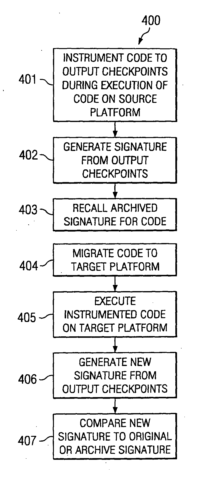
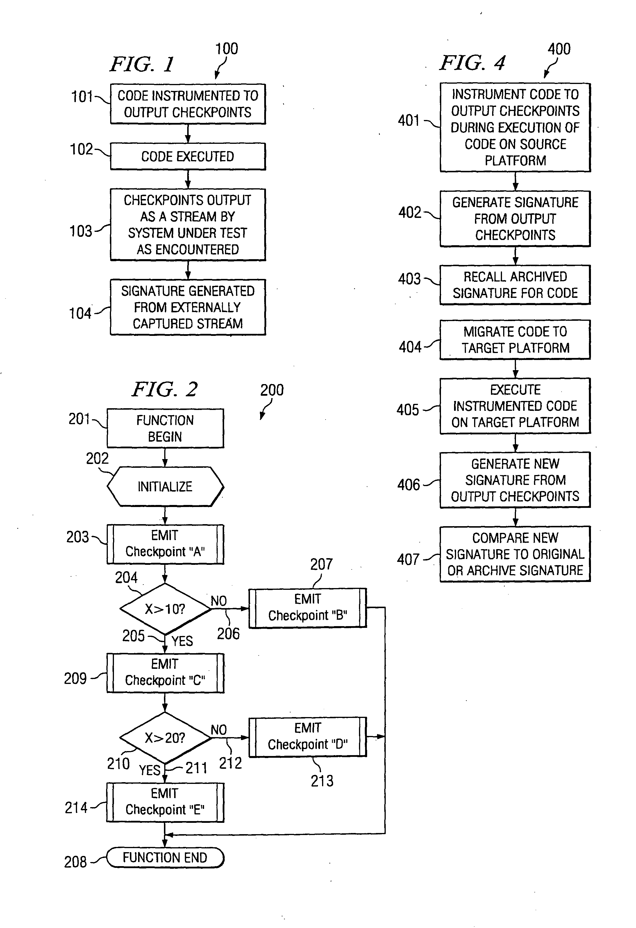
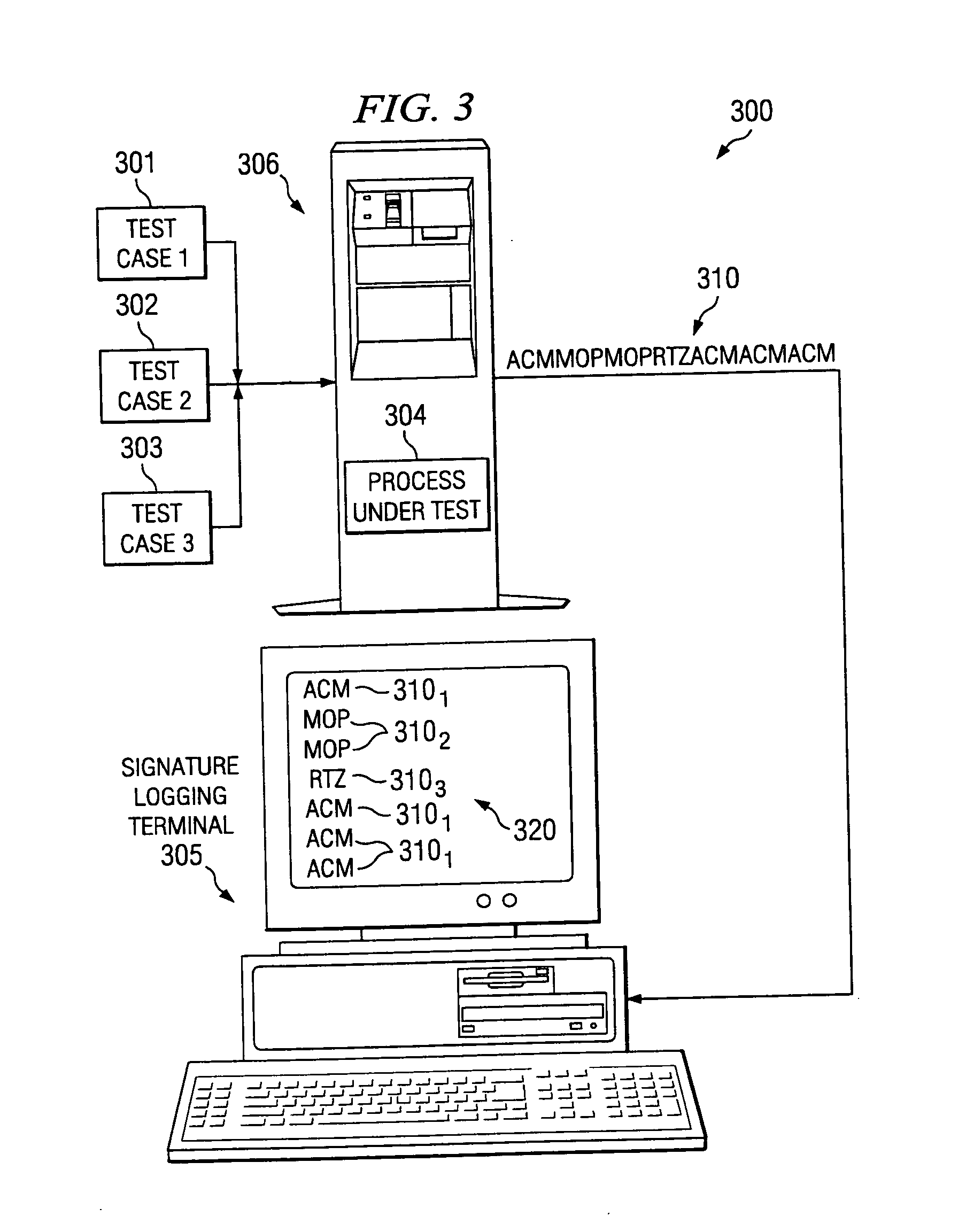
[0017] The present invention provides systems and methods for developing and using software and firmware testing checkpoint signatures. FIG. 1 is a flow chart of an embodiment of a method 100 for providing a checkpoint signature. In accordance with the present invention, code is instrumented to output checkpoints or some internal designations, such as numbers, that are individually unique, at selected points throughout the executing binary, at 101. According to embodiments of the present invention, only one place in the code actually outputs a specific designation such as a number. As code executes at 102 and these checkpoints are reached, these numbers or other designations are produced in a stream at 103. In other words, the first checkpoint to be reached sends out a first number or designation, and a second checkpoint sends out the second number or designation and so on. Thusly, the code generates a unique signature, or map, of the software that may be externally captured at 104 ...


PUM


Abstract

A method for testing code comprises instrumenting code to output checkpoints at selected points during execution of the code on a processor device to derive individual test checkpoints, and generating a signature using the checkpoints.

Description

FIELD OF THE INVENTION [0001] The present invention is generally related to software / firmware testing and specifically related to systems and methods for software and firmware testing using checkpoint signatures. DESCRIPTION OF THE RELATED ART [0002] Forms of software tests known in the art include code coverage, measuring which instructions in a specific software binary that are executed when running certain tests or a group of tests, and test coverage, a measurement of what paths are executed when certain tests get executed. However, when testing high-end embedded server firmware, an operating system (OS) may not be running on the system under test. Once such a computer system has been initialized, the environment may still be very internal to the system, making it very difficult to get data out of the system. The embedded firmware does not have hardware available for its use. Therefore, problems arise with getting data about firmware code execution out of the system under test. [...

Claims


Application Information

Patent Timeline
IPC IPC(8): G06F9/44
CPCG06F11/3688
Inventor QUICK, SHAWN G.
Owner HEWLETT PACKARD DEV CO LP
Learn More