Method of manufacturing yoke of rotary electric machine

Inactive Publication Date: 2005-02-10
DENSO CORP
View PDF13 Cites 8 Cited by
  • Summary
  • Abstract
  • Description
  • Claims
  • Application Information

AI Technical Summary

Benefits of technology

[0030] This invention omits additional chamfering machine work. If a member (e.g. a bracket) to be assembled to the yoke is fitted to the inside of the yoke in the axial direction thereof, the inside corner of the yoke is chamfered. On the other hand, the outside corner of the yoke is chamfered if the member is fitted to the outside of the yoke, so that cracking from the shear drop can be prevented.
[0031] According to a

Problems solved by technology

This may cause the circularity of the yoke to be inaccurate.
If the circularity is not accurate, it is not possible for a rotary electric machine to provide a small air gap between the rotor and the stator thereof.
However, an expe

Method used


Image

  • Method of manufacturing yoke of rotary electric machine
  • Method of manufacturing yoke of rotary electric machine
  • Method of manufacturing yoke of rotary electric machine

Examples


first embodiment

[0063] A method of manufacturing a stator yoke of a starter motor according to the invention is described hereafter. The method of manufacturing a yoke includes steps of cutting, fitting and clamping.

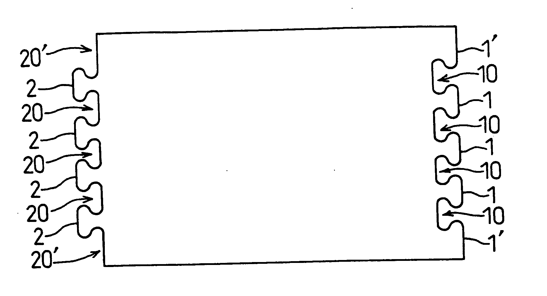
[0064] At the cutting step, a belt like long steel sheet is cut into a rectangular shape having first dovetail convexities 1 on one side thereof and second dovetail convexities 2 on the other side so that they can be fitted to the first dovetail convexities. A press cutter is used to cut the steel sheet in the following manner to have a good yield rate: when the first dovetail convexities 1 are cut at one side, the second dovetail convexities 2 are automatically formed at the other side, as the fragments of the first dovetail convexities.

[0065] As shown in FIG. 1, there are three first dovetail convexities 1 formed at the middle and half-dovetail fragments 1′ and straight portions at the opposite axial ends, on one side (right in FIG. 1) of the cut steel sheet. There are four concaviti...

second embodiment

[0081] A method of manufacturing a yoke according to the invention is described hereafter.

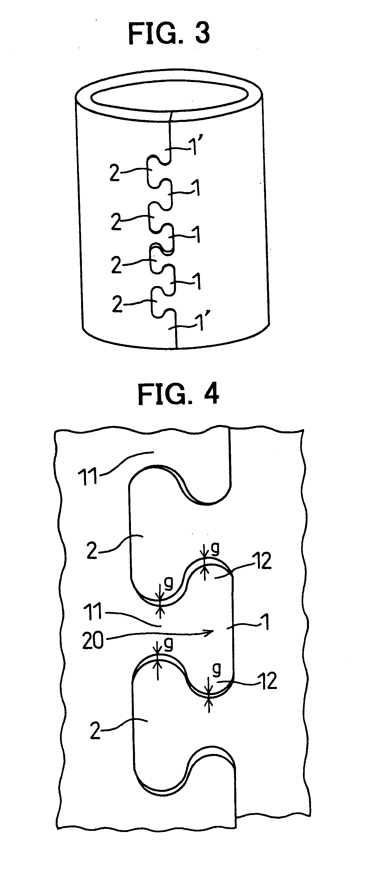
[0082] If the dovetail convexities 1 and 2 formed near the axial edges are punched, the incomplete dovetail convexities 1′ may deform in the axial direction, and a gap G is formed between one and the other sides of the steel sheet at the axial ends of the yoke Y as shown in FIG. 12.

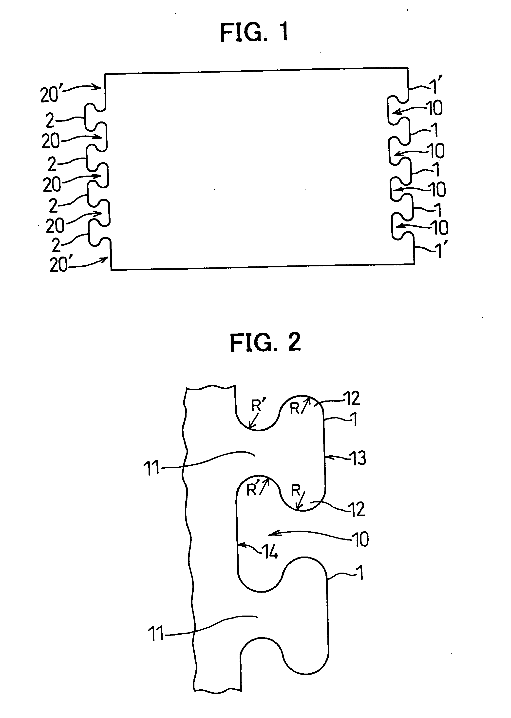
[0083] In the method according to the second embodiment, the portions at axially opposite ends of the first and second dovetail convexities 1 and 2 are not punched, as shown in FIG. 13. That is, the portion along the border of the incomplete dovetail 1′ and the second dovetail 2 is not punched in the clamping step. Others are the same as the embodiment 1.

[0084] Therefore, the incomplete dovetail convexities 1′ fitted to the dovetail convexities 2 at the axial ends of the yoke Y without deforming, so that the clamped portion is not separated. Further, the number of portions being punched in the clamping step can be ...

fourth embodiment

[0090] A method of manufacturing a yoke is described with reference to FIGS. 15-21.

[0091] The method of manufacturing a yoke according to this embodiment has a tube-forming step and a pre-heating step and a painting step in this order, as described in detail below.

[0092] The tube-forming step includes a cutting step and a clamping step.

[0093] In the cutting step, a belt-like long plate is cut by a press machine or a press cutter into a rectangular sheet to form a plurality of convexities 101 at one side and a plurality of concavities 102 to be fitted to the convexities 101 at the other side. When the convexities 101 are formed at one side, the concavities 102 are automatically formed at the other end.

[0094] The one side of the cut sheet (upper side of FIG. 15) has three convexities 101 at the middle thereof, and the other side of the cut sheet (lower side of FIG. 15) has three concavities 102 at the middle thereof.

[0095] The three convexities 101 and the three concavities 102 a...


PUM

PropertyMeasurementUnit
Thicknessaaaaaaaaaa

Abstract

A method of manufacturing a yoke includes a step of cutting a steel plate into a rectangular sheet having a plurality of first dovetail convexities at one end thereof and a plurality of second dovetail convexities at the other end, a step of rolling the rectangular sheet into a cylinder to fit the first dove tails and the second dove tails to each other and a step of punching border portions of the first dove tails and the second dove tails. The second dovetail convexities are formed to be the same in shape as the first dovetail convexities so that they can fit to the first dovetail convexities. A smooth-faced yoke can be manufacture without using an expensive welder.

Description

CROSS REFERENCE TO RELATED APPLICATION [0001] The present application is based on and claims priority from the following Japanese Patent Applications: 2000-277074, filed Sep. 12, 2000; 2000-323201, filed Oct. 23, 2000; and 2000-394893, filed Dec. 26, 2000; the contents of which are incorporated herein by reference. BACKGROUND OF THE INVENTION [0002] 1. Field of the Invention [0003] The present invention relates to a method of manufacturing a stator yoke of a rotary electric machine. [0004] 2. Description of the Related Art [0005] Japanese Patent application JP-A-64-60247 discloses a method of manufacturing a yoke. In the method, a sheet made of magnetic material, such as iron or steel, is rolled and a number of convexities formed at one side thereof are fitted to the same number of concavities. Thereafter, respective central portions of the convexities of one side of the steel sheet are punched and expanded, thereby clamping the opposite sides of the steel sheet. It is also known th...

Claims


Application Information

Patent Timeline
IPC IPC(8): H02K15/02
CPCH02K15/02Y10T29/4902Y10T29/49936Y10T29/49941Y10T29/49945Y10T29/49009Y10T29/49917Y10T29/49Y10T29/49002Y10T29/49893Y10T29/49012
Inventor NIIMI, MASAMIICHIKAWA, HIDEKITAKADA, MASAHIROHOSOYA, AKIFUMIKATOH, MASAHIRO
Owner DENSO CORP
Why Eureka
Try Eureka