Systems and methods for coating optical fiber

a technology of optical fiber and coating material, applied in the field of fiber optics, can solve the problems of affecting the coating effect of the system, the tendency of bubbles to form in the lower viscosity coating material, and the inability to meet the requirements of the application

Inactive Publication Date: 2005-02-10
FURAKAWA ELECTRIC NORTH AMERICA INC
View PDF1 Cites 27 Cited by
  • Summary
  • Abstract
  • Description
  • Claims
  • Application Information

AI Technical Summary

Problems solved by technology

Although systems have been developed in the prior art for applying coating material, these systems suffer from certain limitations.
For example, issues have arisen with respect to coating a fiber with a coating material having a viscosity lower than 100 centipoises.
At higher processing speeds, it has been found that there is a tendency for bubbles to form in lower viscosity coating materials.
These bubbles tend to produce defects in the applied coating.
It has also been found that, at higher processing speeds, it is difficult to maintain the centering of the fiber within the coating.

Method used


Image

  • Systems and methods for coating optical fiber
  • Systems and methods for coating optical fiber
  • Systems and methods for coating optical fiber

Examples


Embodiment Construction

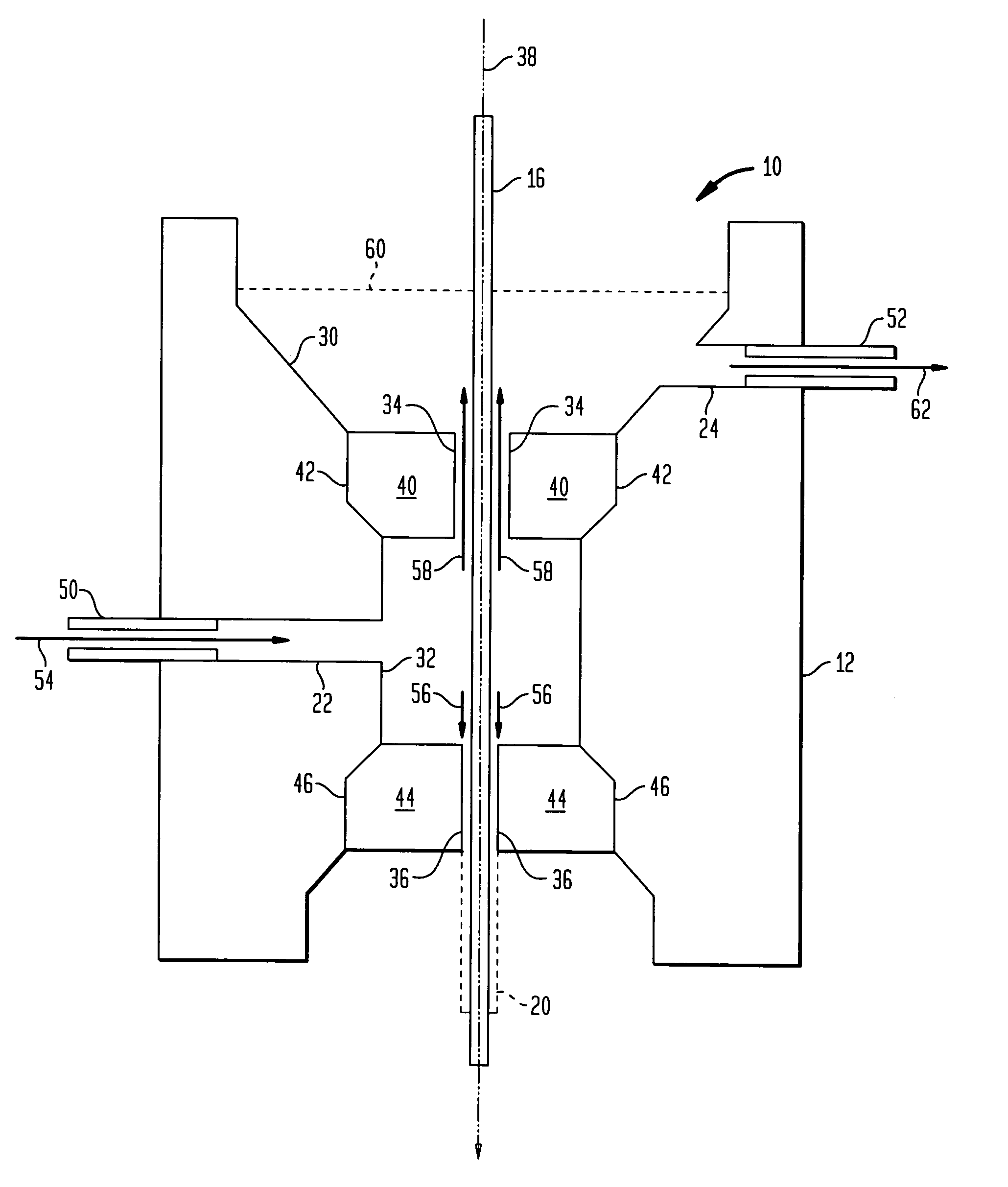
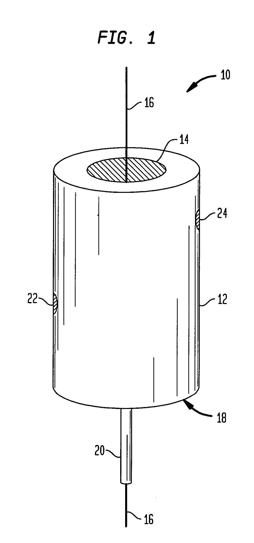
An aspect of the invention provides an apparatus for applying a coating to a fiber. As described below, the apparatus can be used to apply a low viscosity coating material at high speeds, but may also be used with coating materials having higher viscosities. The present invention is described with respect to the application of a coating to an optical fiber as part of a draw process. However, it should be noted that the invention may also be used in other contexts. For example, the invention may be used to apply a coating to an optical fiber outside of a draw tower. The invention may also be used to apply a coating to a fiber or fiber-like structure other than an optical fiber.

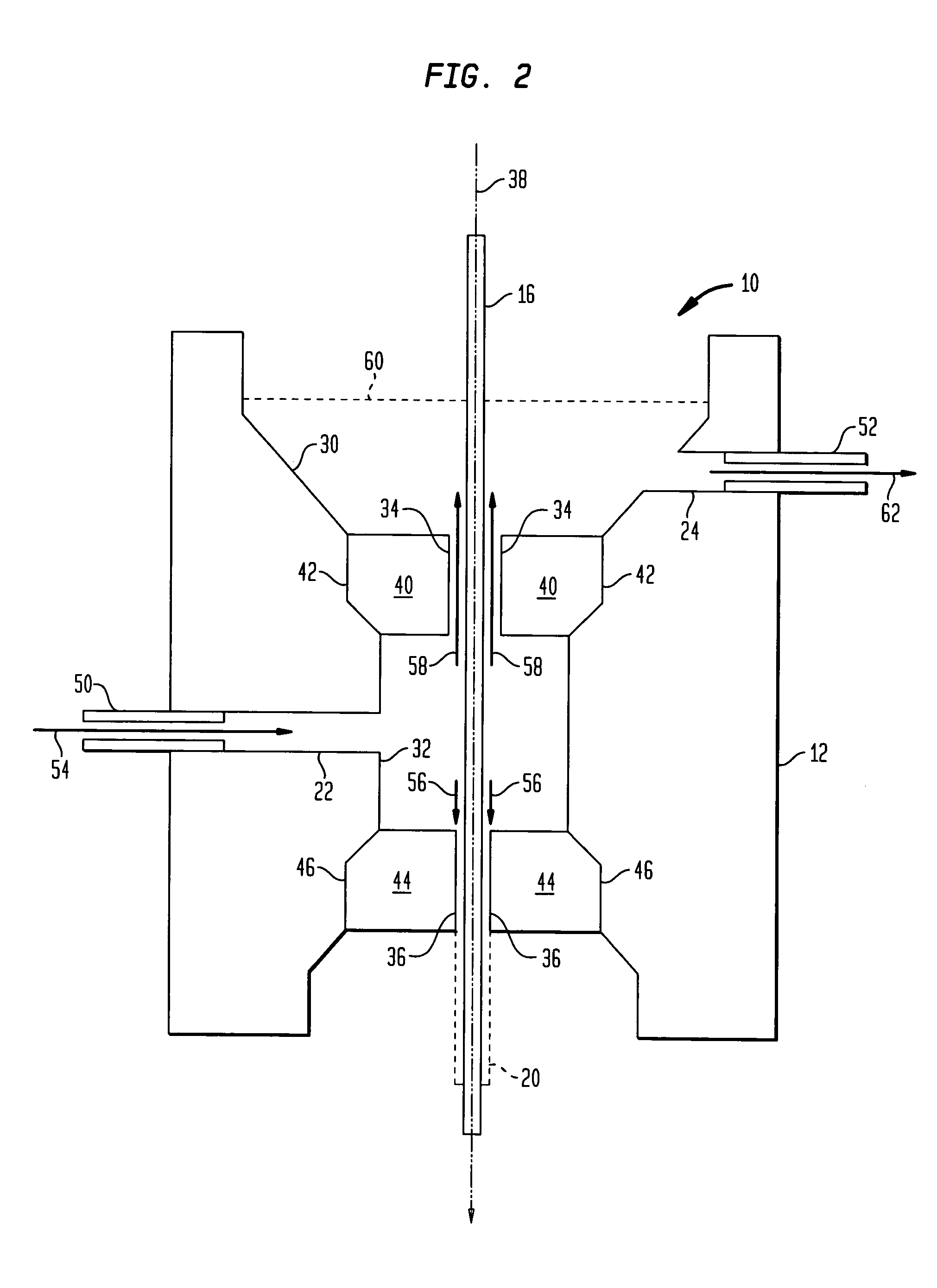
As described in detail below, a coating applicator according to an aspect of the invention provides a semi-pressurized chamber that creates a “counterflow” of coating material in an upward direction opposite to the downward movement of fiber through the applicator. As discussed below, this counterflow reduce...


PUM

PropertyMeasurementUnit
diameteraaaaaaaaaa
diameteraaaaaaaaaa
viscosityaaaaaaaaaa

Abstract

A fiber coating applicator includes a chamber and a cup positioned over the chamber. The cup is connected to the chamber by an entrance aperture. The chamber includes an exit aperture opposite the entrance aperture. The cup, entrance aperture, chamber, and exit aperture define a pathway for a fiber, such as an optical fiber, to be coated. The chamber further includes an input port for pumping a coating material into the chamber. The entrance aperture is dimensioned such that as a fiber travels along the pathway and coating material is pumped into the chamber, coating material travels upward through the entrance aperture around the fiber into the cup, the upward flow of coating material being restricted by the fiber and entrance aperture such that there is a hydrostatic pressure in the chamber. The exit aperture is dimensioned to shape coating material around a fiber traveling along the pathway.

Description

BACKGROUND OF THE INVENTION 1. Field of the Invention The present invention relates generally to improvements in the field of fiber optics, and more particularly to advantageous aspects of systems and methods for applying a coating to an optical fiber. 2. Description of Prior Art Optical fiber is typically coated as part of the manufacturing process. It is advantageous for the coating material to be applied as quickly as possible. However, it is also important for the coating material to be applied uniformly around the fiber, and for the fiber to be centered within the coating material. Although systems have been developed in the prior art for applying coating material, these systems suffer from certain limitations. For example, issues have arisen with respect to coating a fiber with a coating material having a viscosity lower than 100 centipoises. Where a lower viscosity coating material is used, it has proven necessary to reduce processing speeds in order to maintain the qual...

Claims


Application Information

Patent Timeline
Patent Type & Authority Applications(United States)
IPC IPC(8): B05C3/12C03C25/18
CPCC03C25/18B05C3/12
Inventor LINDHOLM, ERIC A.
Owner FURAKAWA ELECTRIC NORTH AMERICA INC
Why Eureka
Try Eureka