Chatter resistant shuttle valve

a technology of shuttle valve and anti-chatter, which is applied in the direction of functional valve types, process and machine control, instruments, etc., can solve the problems of long trouble-free life of underwater shuttle valves, damage to valves and other equipment to which they are connected, and disrupting proper valve operation, etc., to achieve the effect of prolonging the opening tim

Inactive Publication Date: 2005-02-10
PROSERV OFFSHORE INC +1
View PDF4 Cites 45 Cited by
  • Summary
  • Abstract
  • Description
  • Claims
  • Application Information

AI Technical Summary

Benefits of technology

[0006] The present invention involves the provision of a shuttle valve which will provide a smooth opening movement with an extended opening time to help prevent opening of the valve by stray pressure waves. The invention involves the provision of a shuttle valve which does not require the inclusion of additional parts that would be subject to wear or breakage to be added to a shuttle valve to effect the control of shuttle movement. The invention also involves the provision of a shuttle valve which through control of the fit of certain of its parts can be used to control shuttle movement without affecting its normal operation. The invention also involves the provision of a shuttle valve which may be ganged together to form a series of shuttle valves. The present invention also involves the provision of a shuttle valve design which may be utilized as a double ended shuttle valve controlling opening movements in two directions and which design may be used as a shuttle valve which controls the opening movement in only one direction. The present invention also involves the provision of a shuttle valve utilizing a variable volume chamber with restricted access for fluid ingress to control shuttle opening movement.

Problems solved by technology

Certain of the shuttle valves used in such applications were found to have the shuttle oscillate between the valve seats causing chatter during opening movement.
Pressure oscillation can, if of a high magnitude, cause damage to the valve and other equipment to which it is connected, similar to “water hammer” which can occur in certain piping systems with a sudden change in flow for example the sudden closing of a valve.
It is especially important that underwater shuttle valves have a long trouble-free life because of their inaccessibility and the extreme expenses to replace or repair one.
Sometimes a resulting high momentum of a shuttle as it moves uncontrolled from one seat to the other seat creates enough impact to break or crack the cage or cause it to be warped thus disrupting proper valve operation.

Method used


Image

  • Chatter resistant shuttle valve
  • Chatter resistant shuttle valve
  • Chatter resistant shuttle valve

Examples


Embodiment Construction

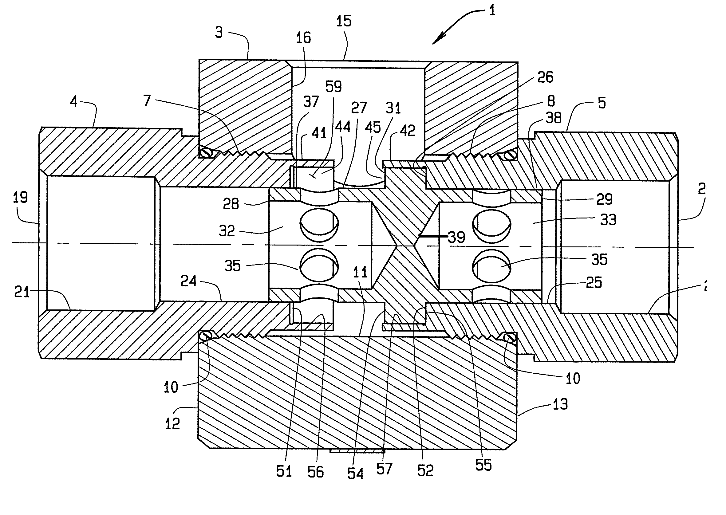
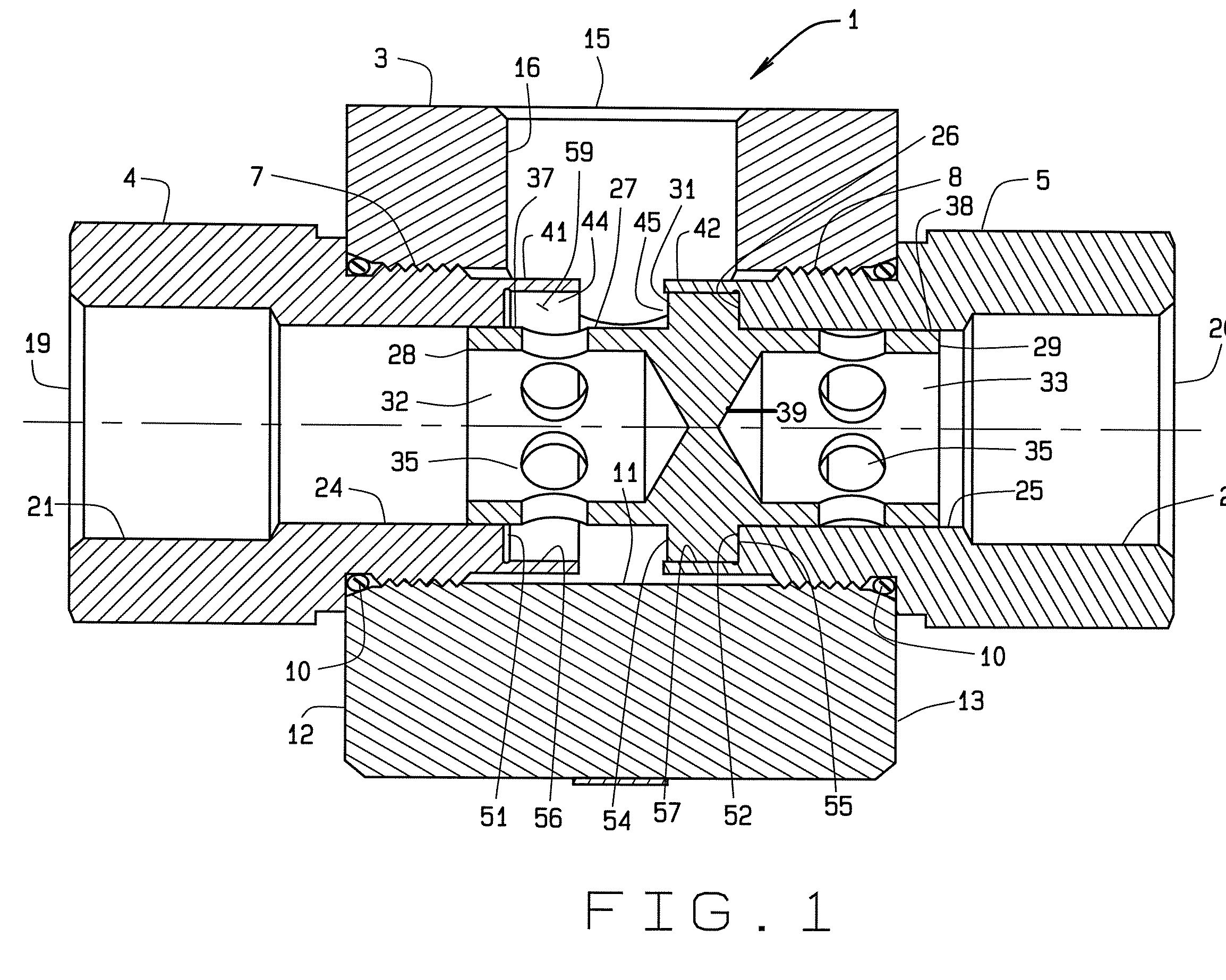
[0019] The valve of FIG. 1 will first be described. The valve, designated generally 1, includes a valve body 3 having mounted therein opposed coaxial adapters 4, 5 mounted to the body 3 as by threaded engagement at 7, 8 respectively. The adapters 4, 5 may be sealed to the body 3 as with O-rings 10 or the like. The body 3 has a throughbore 11 which passes between opposite ends 12, 13 of the body 3. The body 3 is also provided with an outlet 15 which is part of an outlet passage 16 which is shown as generally perpendicular to the bore 11 and connected in flow communication thereto. The adapters 4, 5 each have an inlet 19, 20, respectfully, and a flow passage 21, 22 respectively. Preferably, the passages 16, 21, 22, are round in transverse cross-section, as best seen in FIG. 1 the passage is 21, 22, each have a reduced diameter portion 24, 25 respectively, sized and shaped to receive for axial movement therein, the shuttle 27. The inlets 19, 20 may be connected to source equipment, as ...


PUM


Abstract

A chatter resistant shuttle valve is provided to direct fluid flow from at least two sources of pressurized fluid to a downstream apparatus. The shuttle valve includes a valve body with a shuttle valve member movably mounted inside. A dampening chamber is provided which dampen opening movement of the shuttle as it moved from a closed position on one side of the shuttle toward a closed position on the other end of the shuttle. One or more dampening chambers may be provided.

Description

BACKGROUND OF INVENTION [0001] Shuttle valves are well known in the industry. See for example U.S. Pat. No. 4,253,481 which discloses a cushioned shuttle valve. Shuttle valves generally have two inlets and one outlet. The shuttle valve member inside the valve body moves from a position allowing fluid to flow from a first inlet to the outlet when the pressure in the first inlet is higher than the pressure in a second inlet. When the pressure in the second inlet exceeds the pressure in the flow passage now defined by the first inlet and the outlet, the shuttle will move from its position closing the second inlet to a position closing the first inlet and opening the second inlet thereby changing the flow path. The fluid may also flow in a reverse direction from the outlet to the inlets. [0002] In some applications, particularly those in sub-sea oil production, the ambient pressures operating on the valve may be extremely high in excess of 2,000 psi. Certain of the shuttle valves used i...

Claims


Application Information

Patent Timeline
Patent Type & Authority Applications(United States)
IPC IPC(8): F16K3/26F16K11/07
CPCF16K11/07F16K3/265Y10T137/0502Y10T137/2567Y10T137/7852
Inventor THRASH, THOMAS B. JR.HOPE, RODNEY C.
Owner PROSERV OFFSHORE INC
Why Eureka
Try Eureka