A LED drive circuit and a dimming control method thereof

A LED drive and circuit technology, applied in the field of power electronics, can solve problems such as narrow dimming range, disconnection of SCR for maintaining current, flickering of LED lights, etc.

A LED drive and circuit technology, applied in the field of power electronics, can solve problems such as narrow dimming range, disconnection of SCR for maintaining current, flickering of LED lights, etc.

CN108990213APending Publication Date: 2018-12-11HANGZHOU SILAN MICROELECTRONICS

Image

  • A LED drive circuit and a dimming control method thereof
  • A LED drive circuit and a dimming control method thereof
  • A LED drive circuit and a dimming control method thereof

Examples


Embodiment Construction

[0058] Various embodiments of the invention will be described in more detail below with reference to the accompanying drawings. In the various drawings, the same elements are denoted by the same or similar reference numerals. For the sake of clarity, various parts in the drawings have not been drawn to scale.

[0059] In the present application, the term "chopping period" refers to a period of time when the DC bus voltage is lower than the fourth reference value and the thyristor of the dimmer is in an off state.

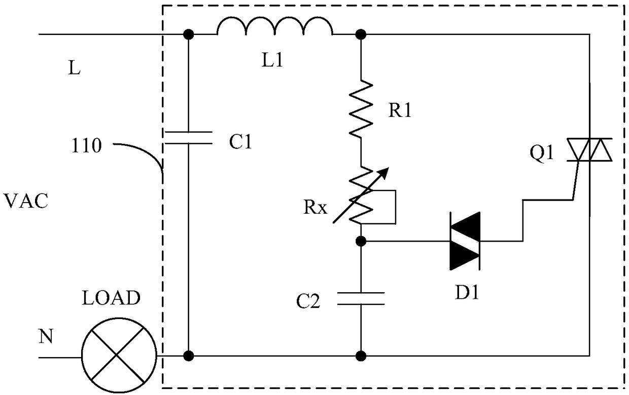
[0060] figure 1 A schematic circuit diagram of a thyristor dimming control system according to the prior art is shown. The thyristor dimming control system includes a dimmer 110 and a load LOAD. The dimmer 110 includes a capacitor C1, an inductor L1, a resistor R1, a variable resistor Rx, a capacitor C2, a bidirectional voltage regulator D1, and a thyristor Q1. The load LOAD is, for example, an incandescent lamp or an LED driving circuit.

[0061] like figure ...


PUM


Abstract

The invention discloses an LED driving circuit and a dimming control method thereof. The LED driving circuit comprises a rectifier bridge for converting an AC input voltage into a DC bus voltage having a half power frequency period; A main circuit connected between the first output terminal and the second output terminal of the rectifier bridge for supplying the load current required by the LED and adjusting the duration of the load current in the half power frequency period according to the DC bus voltage so as to realize dimming; And a drain circuit connected between the first output terminal and the second output terminal of the rectifier bridge for supplying a drain current, wherein the drain circuit controls on and off of the drain current according to the DC bus voltage and the loadcurrent, and the drain current is used for supplying a sustain current of the dimmer. The LED driving circuit adopts different modes to compensate the discharge current according to different conduction angles of the thyristor in the dimmer, thereby suppressing the flicker of the LED lamp, improving the compatibility of the LED driving circuit and the thyristor dimmer, and expanding the dimming range.

Description

technical field [0001] This article relates to related fields of power electronics, in particular, relates to an LED driving circuit and a dimming control method thereof. Background technique [0002] Thyristor dimming technology is a very mature dimming application scheme. Utilizing the characteristics of the thyristor itself, it can be well applied to the dimming of traditional incandescent lamps. It works in two phases, turn-on and turn-off. The working principle is to use the variable resistor R inside the dimmer (that is, the knob or slider) to charge the internal capacitor C. When the voltage on the capacitor C reaches the conduction voltage of the internal thyristor device, the controllable Silicon conduction, at this time, the voltage across the dimmer is almost zero, and all the AC voltage is added to the output of the lamp. Therefore, by adjusting the resistance of the variable resistor R, the RC charging time of the turn-on voltage of the thyristor can be adjus...

Claims


Application Information

Patent Timeline
11 Dec 2018
Publication
CN108990213A
IPC
H05B33/08; H05B44/00
CPC
H05B45/40; H05B45/00; H05B45/3575; Y02B20/30
Inventors
叶美盼; 蔡拥军