Intake air control apparatus for an engine
a control apparatus and engine technology, applied in electrical control, valve housings, instruments, etc., can solve the problems of inability to accurately detect the density of flux change, the inability to obtain the intake air required, etc., and achieve the effect of preventing a variation in outpu
- Summary
- Abstract
- Description
- Claims
- Application Information
AI Technical Summary
Benefits of technology
Problems solved by technology
Method used
Image
Examples
embodiment 2
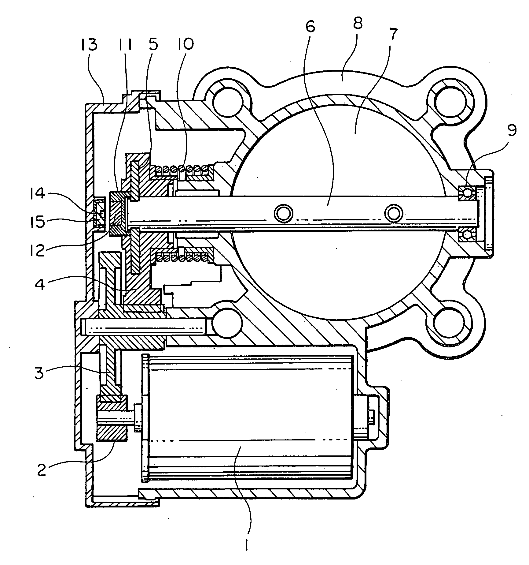
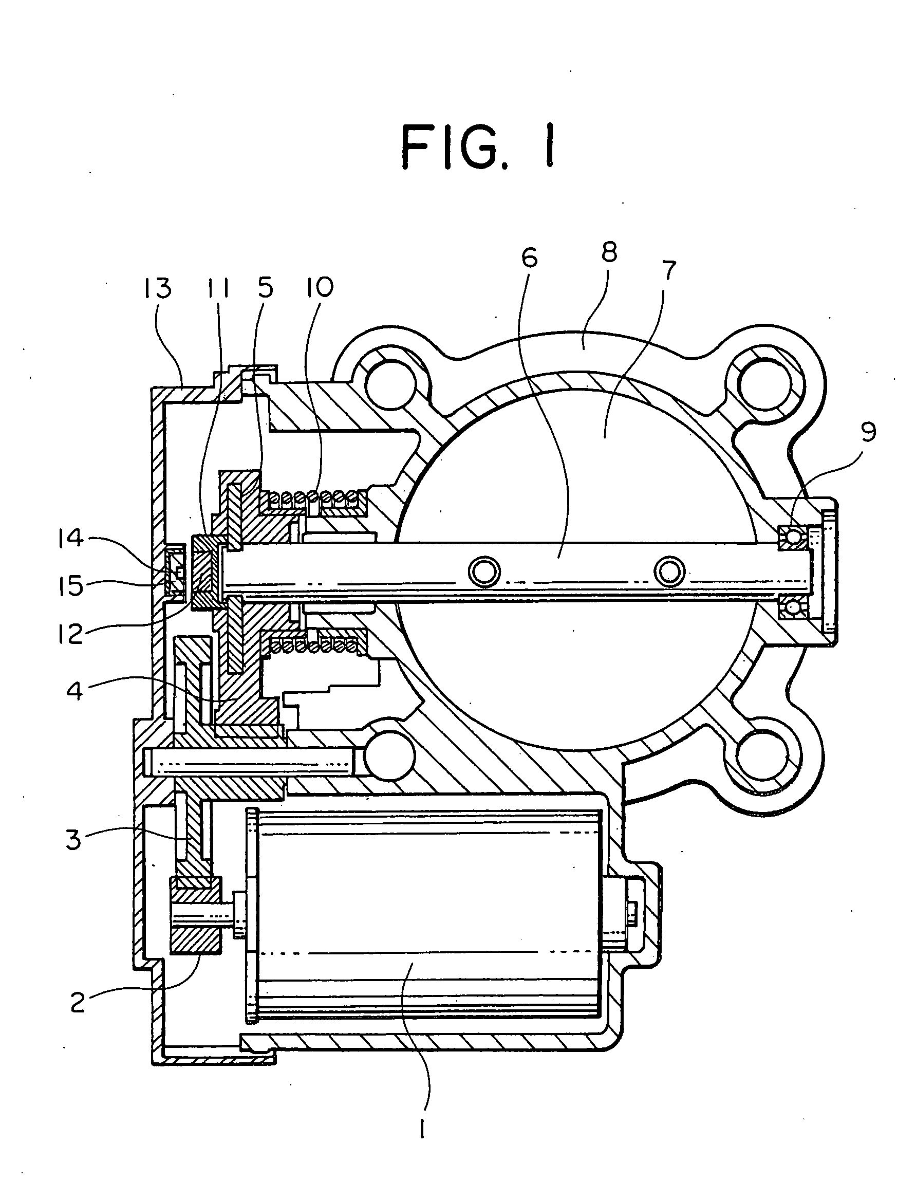
[0034]FIG. 7 is a cross sectional view of essential portions of an intake air control apparatus for an engine according to a second embodiment of the present invention, and FIG. 8 is a view showing the flow of magnetic flux from a permanent magnet 12 in FIG. 7 when viewed in an axial direction of a shaft 6.
[0035] In this embodiment, a bypass member 18 is composed of two members, i.e., a disk-shaped bottom member 19 and a cylinder member 20 of a hollow cylindrical shape that is disposed between the bottom member 19 and the permanent magnet 12 so as to extend from the former toward the latter.
[0036] The bottom member 19 and the cylinder member 20 can be respectively arranged at arbitrary locations, and hence the degree of freedom of their arrangement can be increased, thus making it possible to further reduce the waste of the magnetic flux of the permanent magnet 12. In addition, the influence of external magnetic flux on the sensor 14 can also be further suppressed, thereby contrib...
PUM
 Abstract
Description
Claims
Application Information
 - R&D
- Intellectual Property
- Life Sciences
- Materials
- Tech Scout
- Unparalleled Data Quality
- Higher Quality Content
- 60% Fewer Hallucinations
Browse by: Latest US Patents, China's latest patents, Technical Efficacy Thesaurus, Application Domain, Technology Topic, Popular Technical Reports.
© 2025 PatSnap. All rights reserved.Legal|Privacy policy|Modern Slavery Act Transparency Statement|Sitemap|About US| Contact US: help@patsnap.com


