Front strut air spring suspension system

Inactive Publication Date: 2005-02-10
ARVINMERITOR TECH
View PDF9 Cites 15 Cited by
  • Summary
  • Abstract
  • Description
  • Claims
  • Application Information

AI Technical Summary

Benefits of technology

[0006] The forces upon the spring assembly pass through an upper spring mount, a flange portion of the annular outer bushing, the bearing assembly and into the frame bracket. As the strut isolator assembly does not support the spring assembly, the resilient strut isolator is manufactured of a less dense and more resilient material to provide enhanced isolation.
[0007] An air bag is mounted to a jounce bumper bracket. An annular piston rod seal such as an O-ring seal is mounted about a reduced diameter piston rod segment adjacent a step upon which the jounce bumper bracket is located. The annular piston rod seal is thereby trapped between the step, the annular opening and the inner annular sleeve of the strut isolator assembly. The air

Problems solved by technology

A particular problem encountered by front suspension struts that are mounted to the front steerable wheels is that the upper strut mount must rotate to provide steerage of the front wheels.
Sealing of the air spring rotating upper mount may create complex, unserviceable and/or costly designs which reduces the usable stroke of the strut.
Another disadvantage with convention suspension units is the dif

Method used


Image

  • Front strut air spring suspension system
  • Front strut air spring suspension system
  • Front strut air spring suspension system

Examples


Embodiment Construction

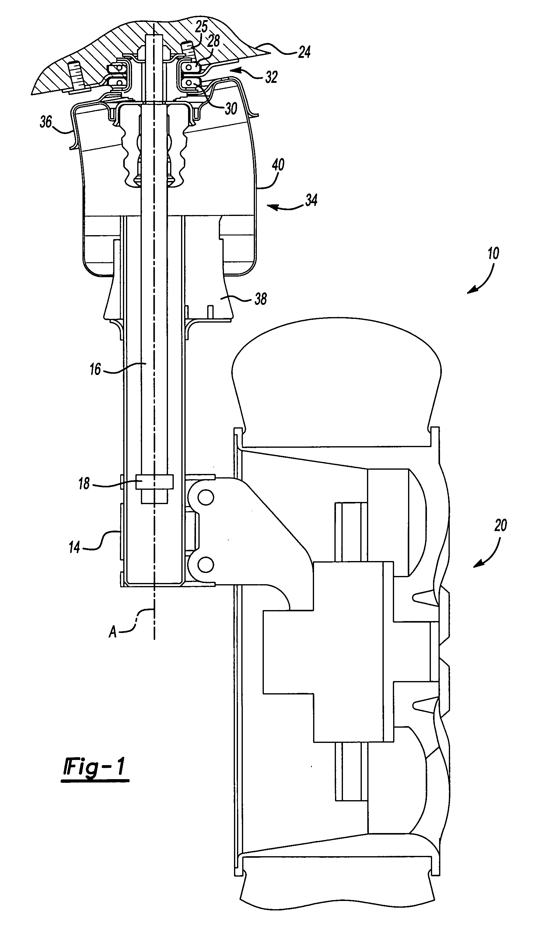
[0015]FIG. 1 illustrates a general partial sectional view of a steerable front suspension system 10. The suspension system 10 includes a fluid shock absorber strut 12 which defines an axis A. The strut 12 includes a cylinder 14 and a piston rod 16 reciprocally mounted therein which reciprocates along axis A. A piston 18 (illustrated schematically) is located within cylinder 14 as generally understood. The cylinder 14 is mounted to a wheel assembly 20.

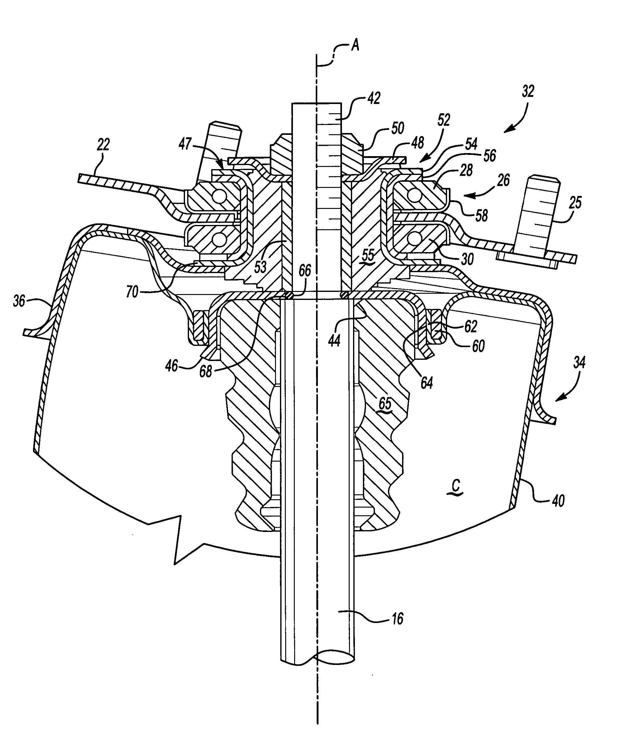
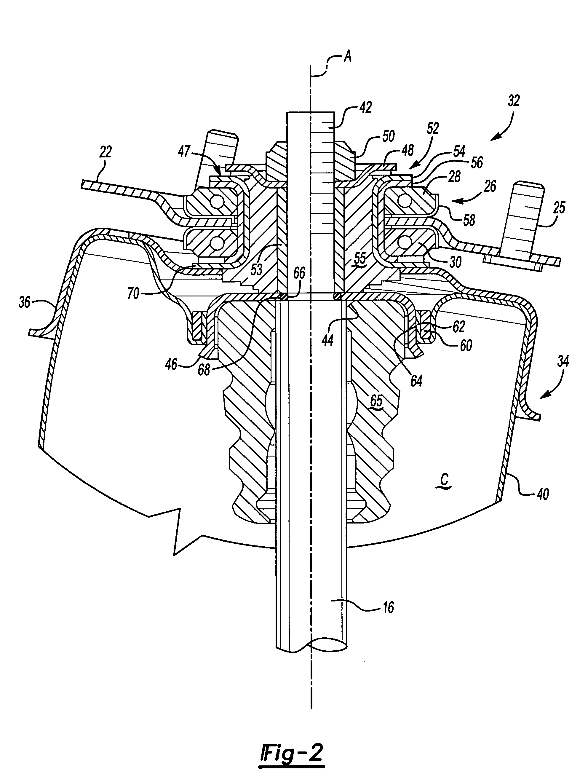
[0016] The piston rod 16 is mounted to a frame bracket 22 which is fixed to a vehicle frame 24 (illustrated schematically) by fasteners 25 or the like. A bearing assembly 26 includes a rebound bearing 28 mounted above the frame bracket 22 and a compression bearing 30 mounted below the frame bracket 22 thereby sandwiching the frame bracket 22 therebetween.

[0017] The bearing assembly 26 is mounted to the piston rod 16 through an upper mount assembly 32 which mounts an air spring assembly 34 thereto. The upper mount assembly 32 supports ...


PUM


Abstract

A steerable front suspension system provides a strut isolator assembly that is supported upon a bearing assembly mounted to a frame bracket. The forces upon a piston rod are transferred to the frame bracket through the strut isolator assembly that is rotationally supported upon the bearing assembly. The forces upon a spring assembly pass through an upper spring mount, a flange portion of the strut isolator assembly, the bearing assembly and into the frame bracket. An air bag is mounted to a jounce bumper bracket. An annular piston rod seal such as an O-ring seal is mounted about a reduced diameter piston rod segment adjacent a step upon which the jounce bumper bracket is located. The air chamber formed by the air bag is thusly sealed to the piston rod by the annular retainer and the annular piston rod seal.

Description

BACKGROUND OF THE INVENTION [0001] The present invention relates to an air spring suspension system, and more particularly to a steerable front suspension system with an air spring and strut fluid shock absorber that provides dual path isolation. [0002] Conventional suspension struts are commonly constructed with either coil springs or air springs mounted adjacent the strut. A particular problem encountered by front suspension struts that are mounted to the front steerable wheels is that the upper strut mount must rotate to provide steerage of the front wheels. Sealing of the air spring rotating upper mount may create complex, unserviceable and / or costly designs which reduces the usable stroke of the strut. [0003] Another disadvantage with convention suspension units is the difficulty of providing a fluid shock absorber strut in combination with an air spring to provide dual path isolation in a compact package or unit on a steerable air strut. Dual path isolation isolates the strut ...

Claims


Application Information

Patent Timeline
IPC IPC(8): B60G1/00B60G3/06B60G11/27B60G15/06B60G15/14B62D1/00
CPCB60G15/068B60G2204/1262B60G2204/1242B60G15/14B60G2204/418
Inventor DEAN, SIMONLLOYD, JEFF
Owner ARVINMERITOR TECH
Why Eureka
Try Eureka