
Gas barrier substrate

a technology of gas barrier and substrate, which is applied in the field of gas barrier substrate, can solve the problems of poor gas barrier property, uneven formation, and difficult to maintain the performance of the display device for a long time, and achieve the effect of high gas barrier property and high quality organic el

Inactive Publication Date: 2005-02-10
DAI NIPPON PRINTING CO LTD
View PDF5 Cites 129 Cited by
  • Summary
  • Abstract
  • Description
  • Claims
  • Application Information

AI Technical Summary

Benefits of technology

The present invention has been achieved in view of the above-mentioned problems, and the main object thereof is to provide a gas barrier substrate having a high gas barrier property and a good flatness without a ruggedness, a pin hole or the like in the gas barrier layer.
According to the present invention, since the organic EL display substrate having the high gas barrier property and flatness is used, the organic EL layer can be formed evenly so that a high quality organic EL device can be provided without deterioration due to the time passage of the organic EL layer without generation or growth of a dark spot or the like.

Problems solved by technology

However, although the plastic substrates are light-weight, flexible and hardly crackable, they have a poorer gas barrier property compared with the glass substrates so that it has been difficult to maintain the performance of the display device for a long time.
Moreover, for example, when a supporting substance is used for a display device such as an organic EL device, the gas barrier property to oxygen or water vapor is required, because the light emission deterioration occur when a light emitting layer of the organic EL device contact with a water vapor or oxygen.
Moreover, when the supporting substrate does not have enough flatness, a defect can be generated in the gas barrier property due to a pin hole, a projection or the like, or since the organic EL layer such as the light emitting layer is a thin film, the organic EL layer cannot be formed evenly due to a pin hole, a projection or the like so that a dark spot is considered to be generated in the organic EL display.
Moreover, when the display is installed and used for a long time, the supporting substrate is required to be stable to the electric potential and the temperature rise.
This is because a problem of the modulation of the light emission or the light of the display can be generated when the supporting substrate is unstable to the electric potential or the temperature rise.
However, according to JP-A Nos. 7-164591, 7-268115, the application is limited to the packaging field such as the food and the medical products.
Furthermore, as to the gas barrier property, the water vapor transmission rate (hereinafter it is referred to also as the WVTR) is about 0.1 g / m2 / day, and the oxygen transmission rate (hereinafter it is referred to also as the OTR) is about 0.3 cc / m2 / day·atm, and thus it is insufficient.
Although the gas barrier property is achieved by providing an inorganic deposition film made of a SiO2 on a substrate, the oxygen transmission rate remains at 1 cc / m2 / day·atm so that it is not sufficient as the water proof property for preventing deterioration of, for example, the light emitting layer of the organic EL device.

Method used


Image

  • Gas barrier substrate
  • Gas barrier substrate
  • Gas barrier substrate

Examples


first embodiment

1. First Embodiment

Firstly, the first embodiment of the gas barrier substrate of the present invention will be explained. The first embodiment of the gas barrier substrate of the present invention comprises a base material, a planarization layer formed on the base material, and a gas barrier layer comprising a deposition film formed on the planarization layer.

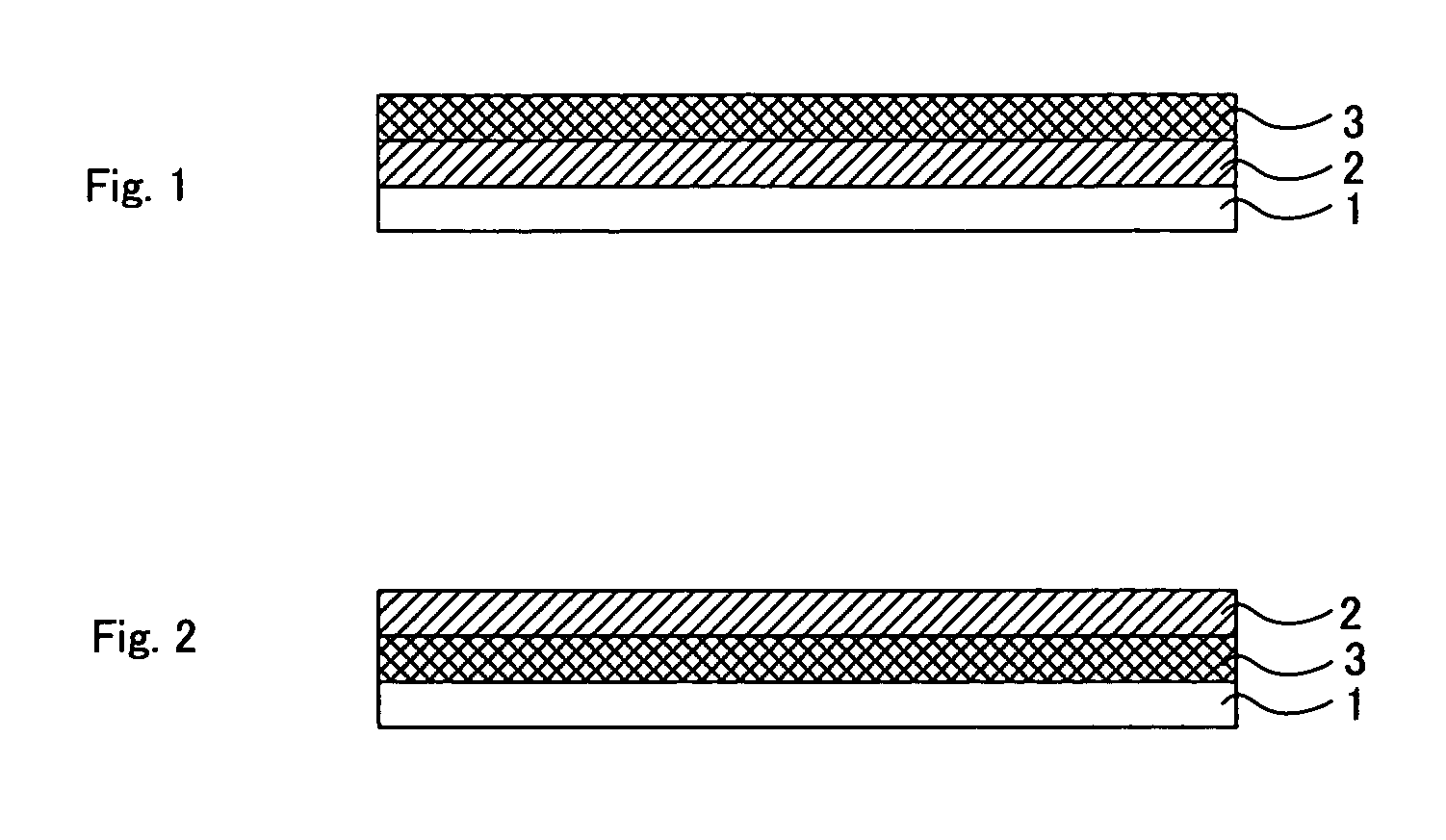
The gas barrier substrate of this embodiment comprises a base material 1, a planarization layer 2 formed on the base material 1, and a gas barrier layer 3 formed on the planarization layer 2 as shown in FIG. 1.

According to this embodiment, since the gas barrier layer is formed on the planarization layer, the dense and flat gas barrier layer can be formed without the influence of the ruggedness or the projection of the base material. Thereby, the gas barrier property of the gas barrier layer can be made higher. Moreover, when the gas barrier substrate of this embodiment is used for a display substrate, one having a high qua...

second embodiment

2. Second Embodiment

Next, the second embodiment of the gas barrier substrate of the present invention will be explained. The second embodiment of the gas barrier substrate of the present invention comprises a base material, a gas barrier layer comprising a deposition film formed on the base material, and a planarization layer, formed on the gas barrier layer, having a cardo polymer.

The gas barrier substrate of this embodiment comprises a base material 1, a gas barrier layer 3 formed on the base material 1, and a planarization layer 2 formed on the gas barrier layer 3 as shown in FIG. 2.

According to this embodiment, since the cardo polymer used for the planarization layer has a high adhesive property to the gas barrier layer so that it can fill a pin hole of the gas barrier layer or the like, thereby a gas barrier substrate having a high gas barrier property can be provided. Moreover, since the planarization layer is formed on the gas barrier substrate surface, it has a flat sur...

third embodiment

1. Third Embodiment

Firstly, the third embodiment of the organic EL device substrate of the present invention will be explained. The third embodiment of the organic EL device substrate of the present invention comprises a base material, a color conversion layer formed on the base material, a planarization layer formed on the color conversion layer, and a gas barrier layer comprising a deposition film formed on the planarization layer. That is, the color conversion layer is formed between the base material and the planarization layer of the gas barrier substrate mentioned in the first embodiment of the “A. Gas barrier substrate”.

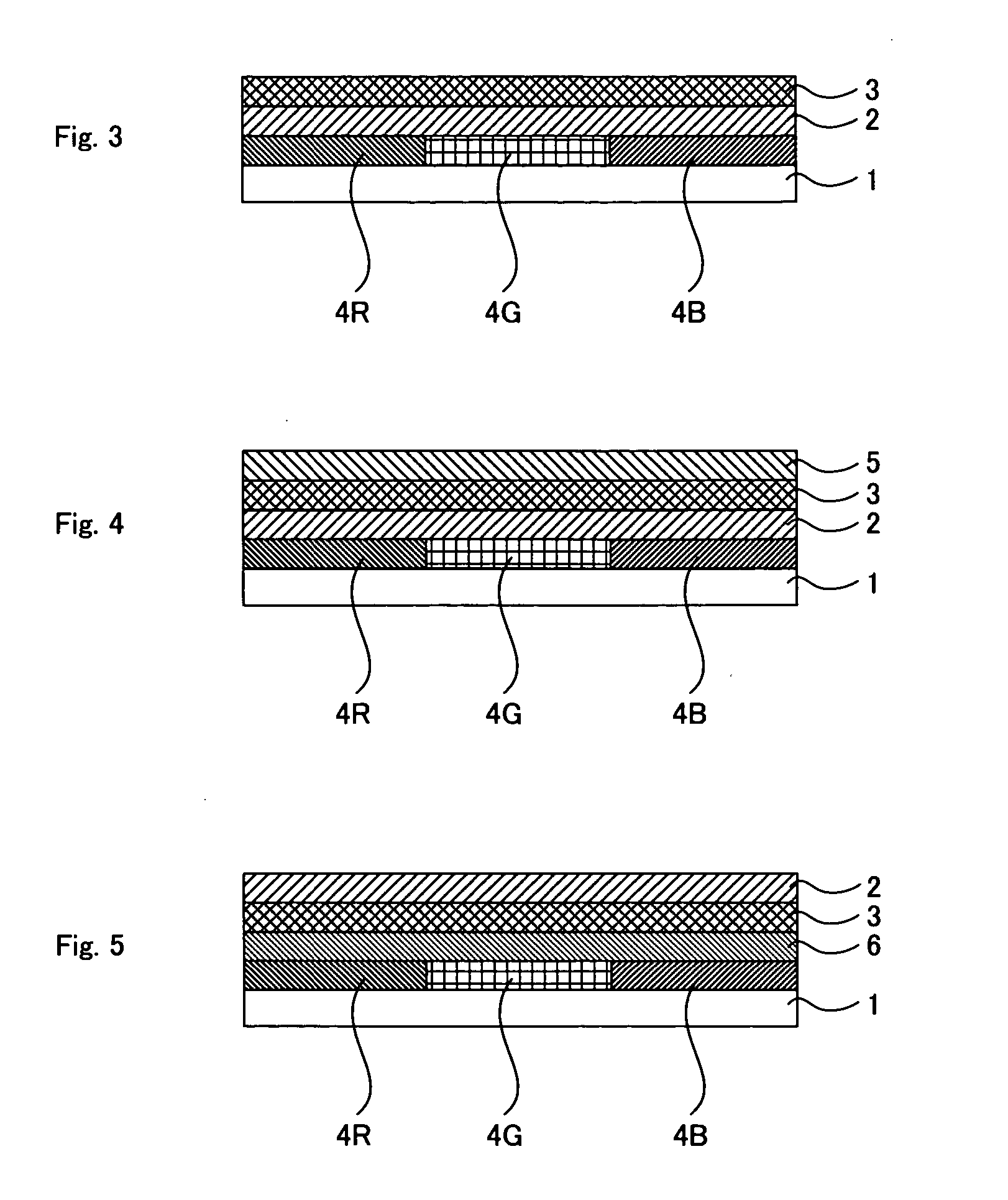
The organic EL device substrate of this embodiment comprises the base material 1, the color conversion layer 4 (4R, 4G and 4B) formed on the base material 1, and the planarization layer 2 formed on the color conversion layer, and the gas barrier layer 3 formed on the planarization layer 2 as shown in FIG. 3.

According to this embodiment, since the gas barr...


PUM

PropertyMeasurementUnit
optical transmittanceaaaaaaaaaa
temperatureaaaaaaaaaa
heat resistant transparentaaaaaaaaaa

Abstract

The main object of the present invention is to provide a gas barrier substrate having a high gas barrier property without a ruggedness, a pin hole or the like in the gas barrier layer. The present invention solves the problem by providing a gas barrier substrate having a base material, a planarization layer formed on the base material, and a gas barrier layer comprising a deposition film formed on the planarization layer.

Description

BACKGROUND OF THE INVENTION 1. Field of the Invention The present invention relates to a gas barrier substrate having a high gas barrier property and a flatness, to be used for a display substrate such as an organic electroluminescent (hereinafter it may abbreviated as organic EL) device or the like. 2. Description of the Related Art Conventionally, for example, as a supporting substrate for a display substrate such as an organic EL display, those using a glass substrate are known. However, the glass substrates have shortcomings of heaviness, hardness and easily crackable. Then, recently, in order to solve the problems of the glass substrates, a plastic substrate has been proposed. However, although the plastic substrates are light-weight, flexible and hardly crackable, they have a poorer gas barrier property compared with the glass substrates so that it has been difficult to maintain the performance of the display device for a long time. Moreover, for example, when a supporti...

Claims


Application Information

Patent Timeline
Patent Type & Authority Applications(United States)
IPC IPC(8): C23C14/02H01L27/32H01L51/52
CPCC23C14/024H01L27/322H01L51/5237H01L2251/5338Y10T428/12007Y10T428/24355Y10T428/12493Y10T428/24479Y10S428/917H10K59/38H10K2102/311H10K59/873H10K50/844
Inventor KAWASHIMA, SAYAKAKOMADA, MINORUTOKUNAGA, KEIJI
Owner DAI NIPPON PRINTING CO LTD
Learn More