Fluid-pressure brake system for a vehicle

a brake system and fluid pressure technology, applied in the direction of brake cylinders, anti-theft devices, braking systems, etc., can solve the problems of increased manufacturing and assembly complexity during installation, increased risk of failure of the brake system, and increased costs

Inactive Publication Date: 2005-02-10
WABCO GMBH
View PDF3 Cites 121 Cited by
  • Summary
  • Abstract
  • Description
  • Claims
  • Application Information

AI Technical Summary

Benefits of technology

[0007] A further advantage of the present invention is that the parking brake module can be integrated in simple manner not only into electrically controlled brake systems (EBSs) but also, in equally simple manner, into conventional air-brake systems with or without anti-lock brake systems (ABSs).
[0008] According to another advantageous embodiment of the present invention, the electrically actuatable valve device is provided with a bistable valve having a bistable switching function with two operating states. In the first operating state, a fluid can be fed to the actuator that operates the wheel brake. In the second operating state, fluid can be removed from the actuator. The use of such a bistable valve has the advantage that, in the event of failure or malfunction of the on-board voltage supply, the valve remains in its last established operating state. Unlike conventional systems employing valves having a set normal operating position in the event of electrical power failure, the use of the bistable valve according to the present invention has the advantage that it enables complian

Problems solved by technology

Such an arrangement of additional valves in an air-brake system of a vehicle leads to increased manufacturing and assembly complexity during installation of the brake s

Method used


Image

  • Fluid-pressure brake system for a vehicle
  • Fluid-pressure brake system for a vehicle
  • Fluid-pressure brake system for a vehicle

Examples


Embodiment Construction

[0021] The present invention will be explained hereinafter in the context of an electrically controlled brake system. It should be appreciated, however, that the present invention has application with respect to brake systems that are not electrically controlled.

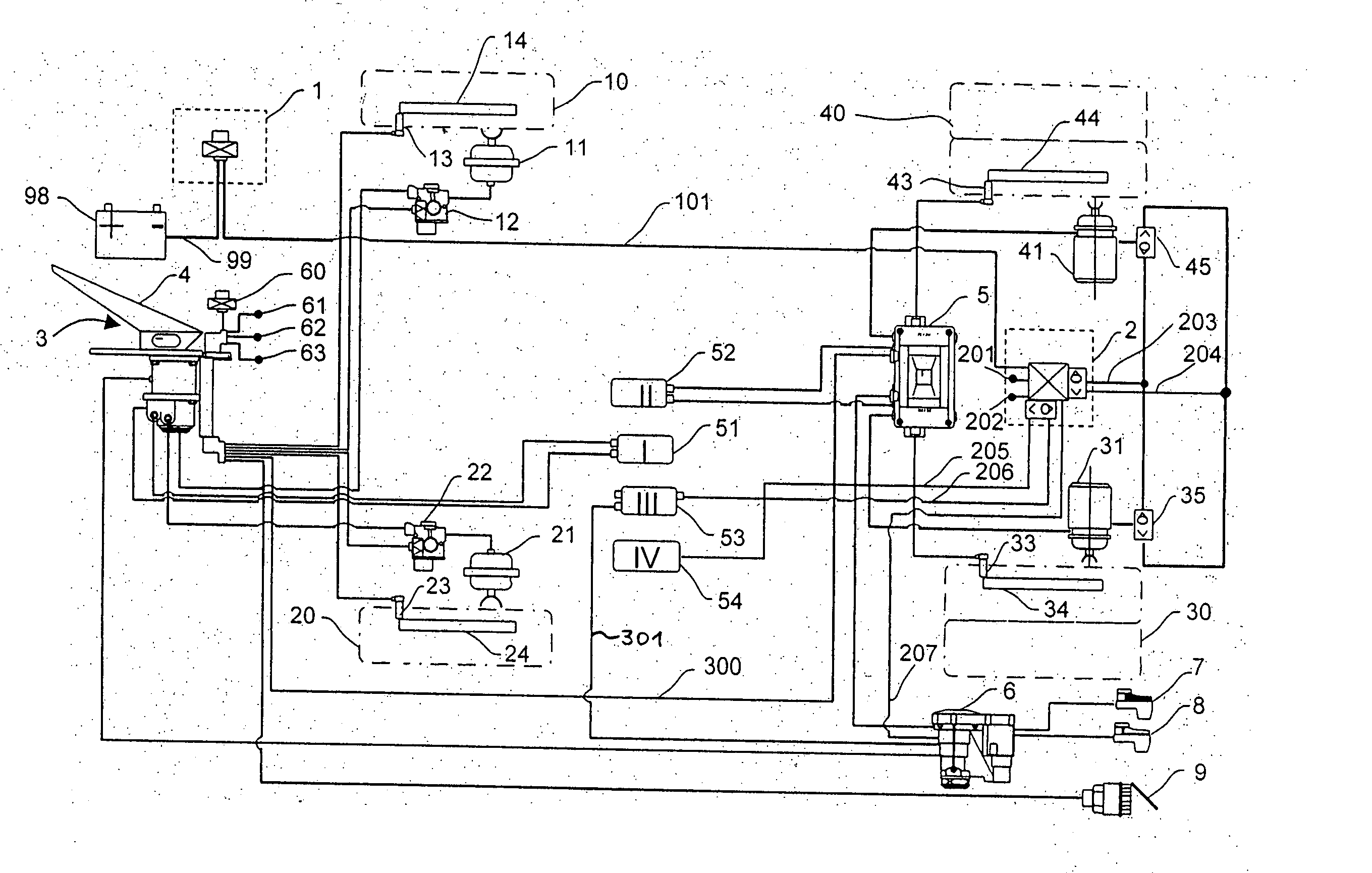
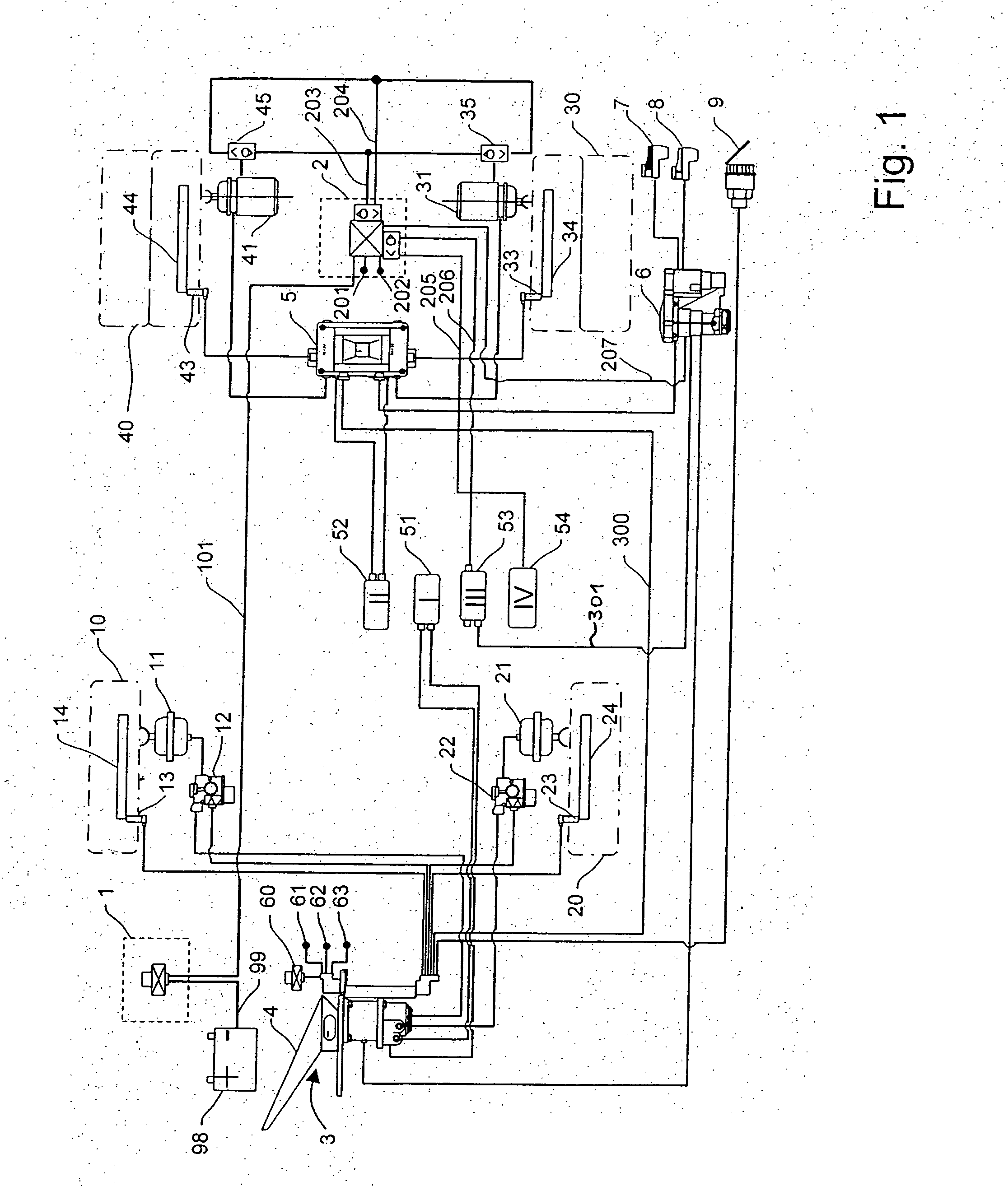
[0022] Referring now to the drawing figures, where like and corresponding parts are denoted by like reference numerals, FIG. 1 is a schematic diagram depicting an air-brake system for a four-wheel vehicle. The vehicle brake system depicted in FIG. 1 is of the electrically controlled type. That is, the injection of brake pressure to the individual wheel brakes is controlled by electrical / electronic control elements.

[0023] The vehicle depicted to FIG. 1 has four wheels 10, 20, 30, 40, each equipped with a wheel brake to permit individual braking. Wheels 10, 20, also referred to hereinafter as “front wheels,” are allocated to the front axle of the vehicle. Wheels 30, 40, also referred to hereinafter as “rear wheels,” are allo...


PUM


Abstract

A fluid-pressure brake system for a vehicle having a parking brake function in which, in response to actuation of an electrical parking brake signal transmitter, and without actuation of a brake pedal, at least one wheel brake of the brake system is actuated via an actuator to which the fluid is admitted. A parking brake module is provided in which there is integrated an electronic control unit as well as valve devices that are electrically actuatable by the electronic control unit. The electronic control unit actuates the parking brake function upon receiving from the parking brake signal transmitter an electrical actuating signal demanding actuation of the parking brake function and, as part of the parking brake function, the electronic control unit controls the admission of fluid to the actuator by means of the electrically actuatable valve devices.

Description

BACKGROUND OF THE INVENTION [0001] The present invention relates to a fluid-pressure brake system for a vehicle. [0002] DE 198 57 393 A1 describes a conventional vehicle air-brake system provided with a parking brake device. The system described in DE 198 57 393 functions without pneumatic lines to a parking brake actuating element used for actuation of the parking brake device by the vehicle driver. Typically, the parking brake actuating element is designed as a pneumatic valve that can be manually operated. In the parking brake device described in DE 198 57 393 A1, signals for actuation of the parking brake are transmitted electrically, thus obviating the need for installation of pneumatic lines in the driver's cab. [0003] The parking brake function described in DE 198 57 393 A1 is achieved by providing a plurality of conventional solenoid valves via which the brake cylinders or the spring actuators of the vehicle's brake system can be acted on by compressed air. Such an arrangeme...

Claims


Application Information

Patent Timeline
IPC IPC(8): B60T7/10B60T13/26B60T13/68B60T17/22
CPCB60T7/10B60T17/221B60T13/68B60T13/263
Inventor BENSCH, UWEKIEL, BERNDROSENDAHL, HARTMUTFORSTER, HENNINGMENZE, WILFRIEDSTRUWE, OTMAR
Owner WABCO GMBH
Why Eureka
Try Eureka