Impedance measuring circuit and capacitance measuring circuit

a capacitance measuring circuit and impedance measurement technology, applied in the field of circuits, can solve problems such as detection errors and increased errors, and achieve the effect of reducing noise mixed and reducing stray capacitan

Inactive Publication Date: 2005-02-10
HOKUTO ELECTRONICS +1
View PDF4 Cites 13 Cited by
  • Summary
  • Abstract
  • Description
  • Claims
  • Application Information

AI Technical Summary

Benefits of technology

[0011] In order to reduce noise mixed in the signal line that connects the impedance detection circuit and the impedance to be detected, and also reduce the stray capacitance b...

Problems solved by technology

However, when very small capacitance, which equals to or is less than an order of several pF or fF (femtofarad), is detected, an error is increased.
Also, depending on a frequency of the AC voltage Vac applied, a subtle displacement of a phase and amplitude ...

Method used


Image

  • Impedance measuring circuit and capacitance measuring circuit
  • Impedance measuring circuit and capacitance measuring circuit
  • Impedance measuring circuit and capacitance measuring circuit

Examples


first embodiment

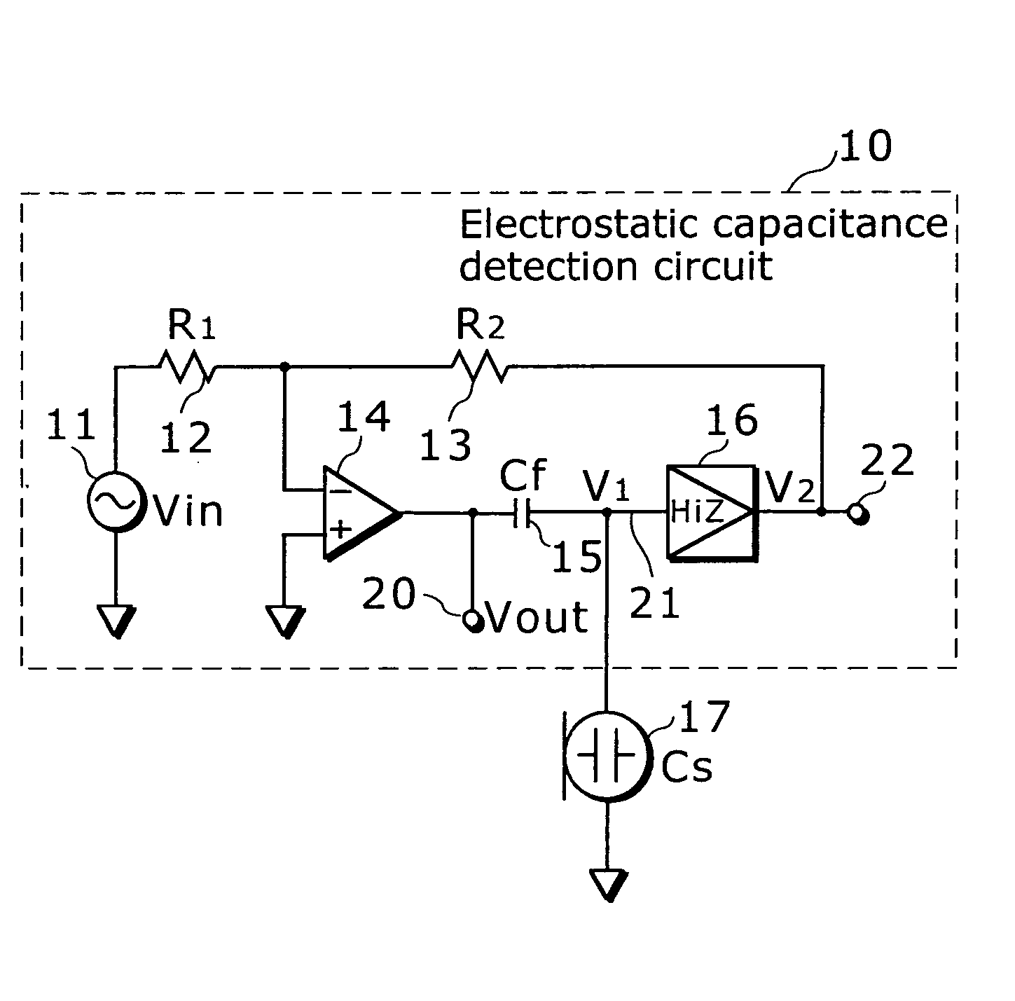
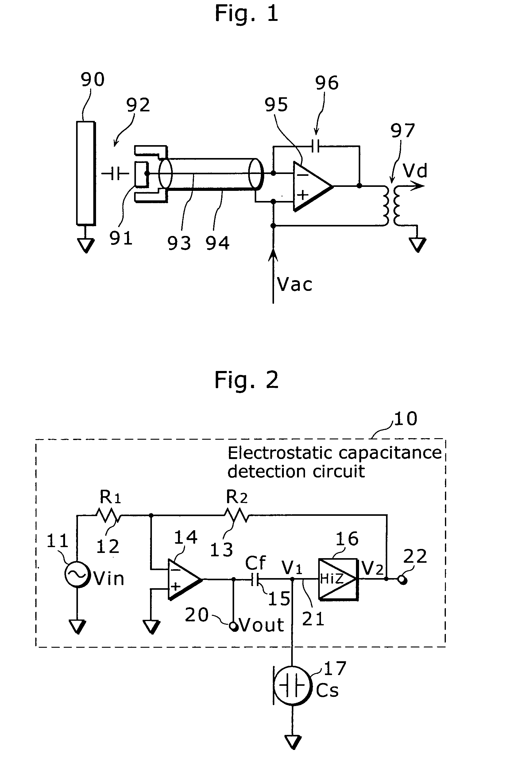
[0022]FIG. 2 is a circuit diagram of an impedance detection circuit according to a first embodiment of the present invention. In this diagram, an electrostatic capacitance detection circuit 10 as this impedance detection circuit is connected to a capacitor to be detected 17 as impedance to be detected that is a subject for detection (i.e. a capacitance type sensor that detects various types of physical quantities using a fluctuation in the electrostatic capacitance Cs such as a capacitor microphone in this example).

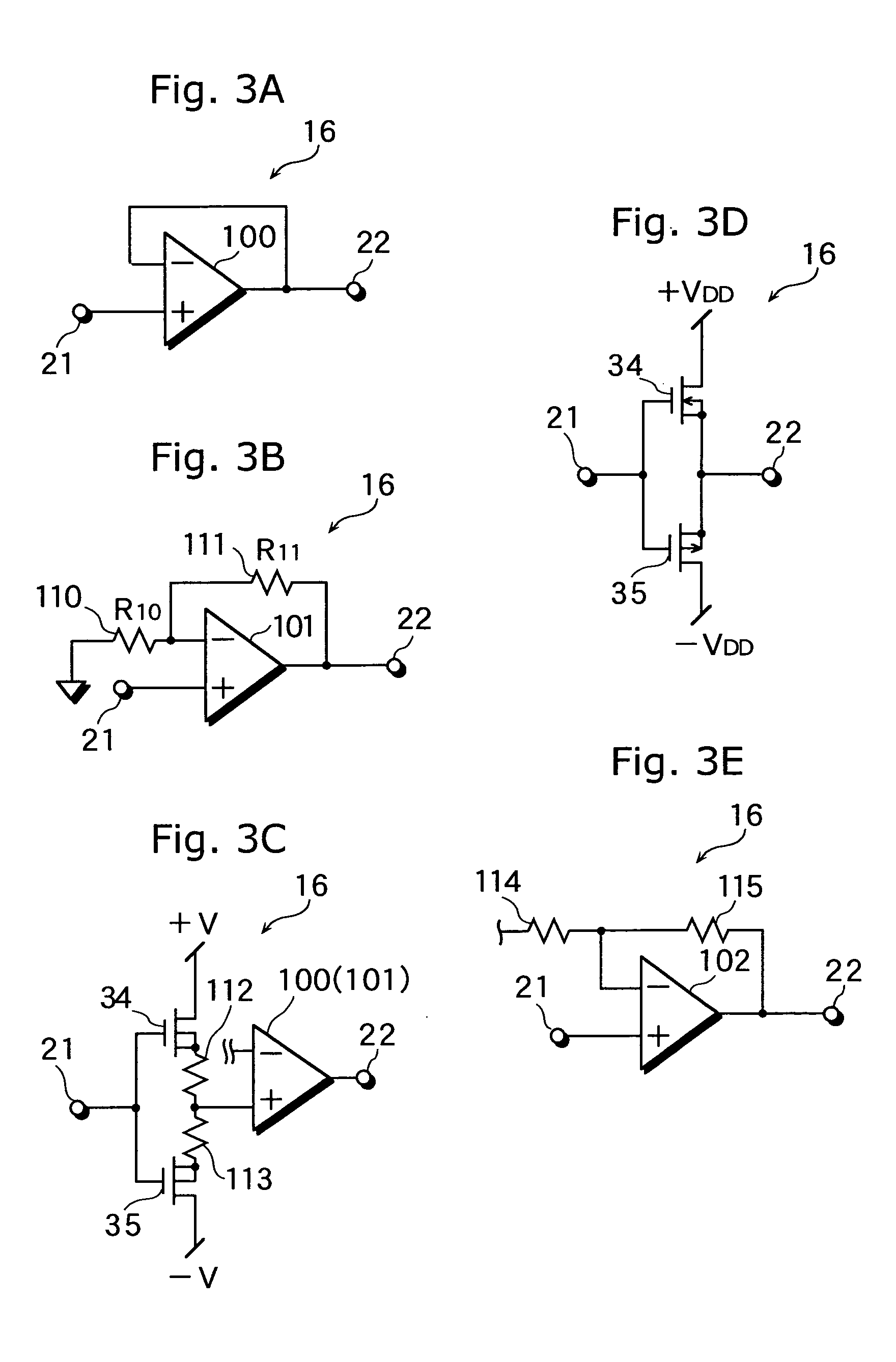
[0023] This electrostatic capacitance detection circuit 10 comprises an AC voltage generator 11 that generates AC voltage, a resistance (R1) 12, a resistance (R2) 13, an operational amplifier 14, an impedance element 15 (a capacitor with capacitance Cf in this example) and an impedance converter 16, and outputs a detection signal (voltage V out) corresponding to electrostatic capacitance of the capacitor 17 from a signal output terminal 20.

[0024] One end of the AC volta...

second embodiment

[0044] Next, the following describes an electrostatic capacitance detection circuit according to a second embodiment of the present invention.

[0045]FIG. 4 is a circuit diagram of an electrostatic capacitance detection circuit 30 as an impedance detection circuit in the second embodiment. This electrostatic capacitance detection circuit 30 is roughly composed of a core unit 31 that is equivalent to the electrostatic capacitance detection circuit 10 as the impedance detection circuit shown in FIG. 2, an inverting unit 32 that receives signal voltage V01 at a signal output terminal 20 of the core unit 31 as an input and inverts the signal voltage V01, an adding unit 33 that adds up signal voltage V03 at an output terminal 23 of the inverting unit 32 and signal voltage V02 at an AC output terminal 22 of the core unit 31 and outputs a detection signal of voltage V04 to an output terminal 24.

[0046] The core unit 31 has the same circuit as the electrostatic capacitance detection circuit ...


PUM


Abstract

An electrostatic capacitance detection circuit 10 comprises an AC voltage generator 11, an operational amplifier 14 of which non-inverting input terminal is connected to specific potential (a ground in this example), an impedance converter 16, a resistance (R1) 12 connected between the AC voltage generator 11 and an inverting input terminal of the operational amplifier 14, a resistance (R2) 13 connected between the inverting input terminal of the operational amplifier 14 and an output terminal of the impedance converter 16, and an impedance element (a capacitor) 15 connected between an output terminal of the operational amplifier 14 and an input terminal of the impedance converter 16. A capacitor to be detected 17 is connected between the input terminal of the impedance converter 16 and the specific potential.

Description

TECHNICAL FIELD [0001] The present invention relates to a circuit that detects impedance, especially relates to the circuit that detects very small impedance with high accuracy. BACKGROUND ART [0002] As a prior art of an electrostatic capacitance detection circuit, that described in Japanese Laid-Open Patent Application H09-280806 gazette can be cited. FIG. 1 is a circuit diagram that shows this electrostatic capacitance detection circuit. In this detection circuit, a capacitive sensor 92 comprised of electrodes 90 and 91 is connected to an inverting input terminal of an operational amplifier 95 via a signal line 93. And a capacitor 96 is connected between an output terminal of this operational amplifier 95 and the said inverting input terminal, and further an AC voltage Vac is applied to a non-inverting input terminal. Also, the said signal line 93 is wrapped up by a shield line 94 and shielded electrically against disturbance noise. And this shield line 94 is connected to the non-...

Claims


Application Information

Patent Timeline
IPC IPC(8): G01D5/24G01N27/22G01R27/26
CPCG01D5/24G01N27/22G01R27/2605G01R27/26
Inventor YAKABE, MASAMIIKEUCHI, NAOKIMATSUMOTO, TOSHIYUKINAKANO, KOICHI
Owner HOKUTO ELECTRONICS
Why Eureka
Try Eureka