Filter device and branching filter using same

a filter device and branching filter technology, applied in the direction of piezoelectric/electrostrictive/magnetostrictive devices, electrical apparatus, impedence networks, etc., can solve the problem of difficulty in achieving further higher frequency operations by using the saw filter, the filter using the piezoelectric film has not been used in high frequency applications, and it is difficult to fabricate the thin piezoelectric film with high accuracy. such material, and achieves low power loss, small size, and low area occupied

Active Publication Date: 2005-02-10
SNAPTRACK
View PDF7 Cites 125 Cited by
  • Summary
  • Abstract
  • Description
  • Claims
  • Application Information

AI Technical Summary

Benefits of technology

[0013] In view of the above, it is an object of the present invention to provide a filter device which is low in power loss and small in size and can operate in a wide band.

Problems solved by technology

Therefore, it is thought that, achievement of operations in a further higher frequency by using the SAW filter has a difficulty.
Since ceramic or quarts is conventionally used as a material for the piezoelectric film, it was difficult to fabricate the thin piezoelectric film with high accuracy using such the material and, therefore, the filter using the piezoelectric film has not been used in high frequency applications.
However, the conventional filter device has problems.
The SCF, since it is a filter that operates in a narrow band, is not suitable for a filter that should operate in a wide band.
The CRF, since it uses multiple modes, is suitable for a filter that should operate in a wide band, however, it suffers larger insertion loss due to its operational principles when compared with the case of the conventional ladder-type filter and, therefore, is not suitable for a filter that should be low in power loss.

Method used


Image

  • Filter device and branching filter using same
  • Filter device and branching filter using same
  • Filter device and branching filter using same

Examples


first embodiment

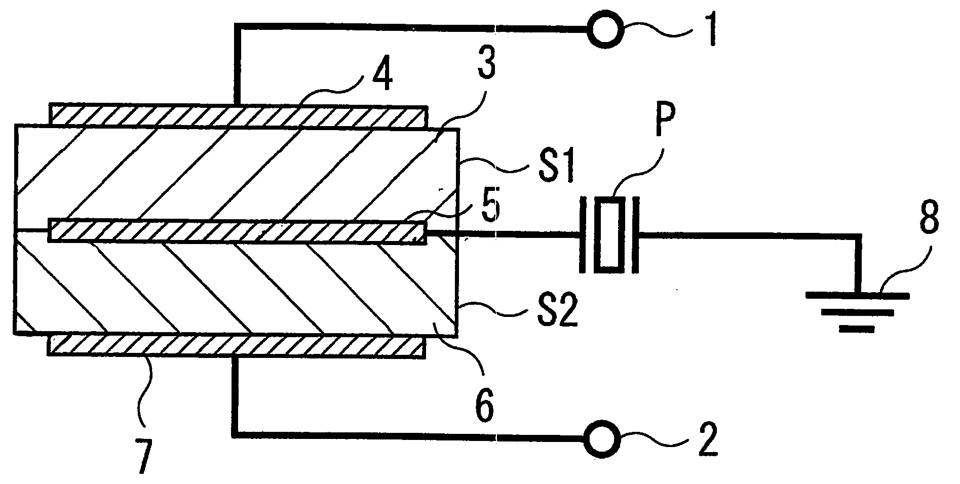
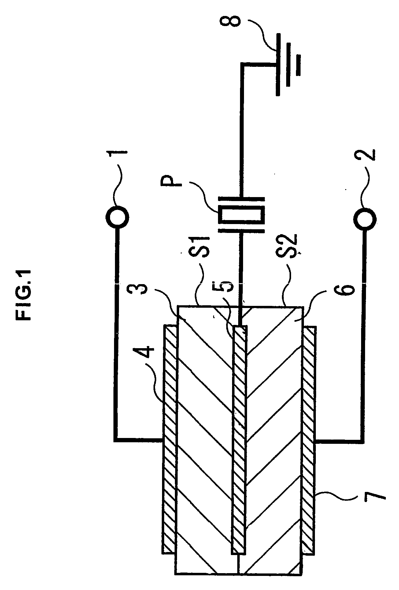
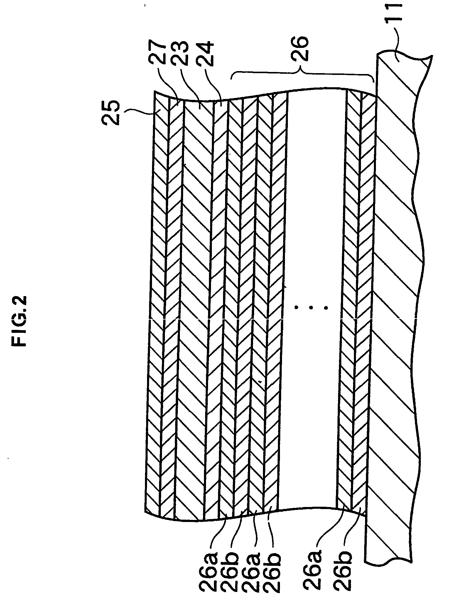
[0191]FIG. 1 is a diagram showing one example of configurations of a filter device according to a first embodiment of the present invention. FIG. 2 is a cross-sectional view illustrating a piezo-resonator making up the filter device shown in FIG. 1. FIG. 3 is a diagram showing an equivalent circuit of the filter device shown in FIG. 1. FIG. 4 is a graph showing a frequency characteristic of the filter device shown in FIG. 1. FIG. 5 is a diagram schematically showing another example of the configurations of the filter device according to the first embodiment. FIG. 6 is a diagram showing an equivalent circuit of the filter device shown in FIG. 5. FIG. 7 is a diagram schematically showing still another example of the configurations of the filter device according to the first embodiment. FIG. 8 is a diagram showing an equivalent circuit of the filter device shown in FIG. 7. FIG. 9 is a diagram schematically showing still another example of the configurations of the filter device of the ...

second embodiment

[0217]FIG. 11 is a diagram showing one example of configurations of a filter device according to a second embodiment of the present invention. FIG. 12 is a diagram showing an equivalent circuit of the filter device shown in FIG. 11. FIG. 13 is a graph showing a frequent characteristic of the filter device shown in FIG. 11. FIG. 14 is a diagram showing another example of configurations of the filter device according to the second embodiment. FIG. 15 is a diagram showing an equivalent circuit of the filter device shown in FIG. 14. FIG. 16 is a diagram showing still another example of configurations of the filter device according to the second embodiment. FIG. 17 is a diagram showing an equivalent circuit of the filter device shown in FIG. 16. FIG. 18 is a diagram showing still another example of configurations of the filter device according to the second embodiment. FIG. 19 is a diagram showing an equivalent circuit of the filter device shown in FIG. 18.

[0218] As shown in FIG. 11, in...

third embodiment

[0237]FIG. 20 is a diagram schematically showing one example of configurations of a filter device of a third embodiment of the present invention. FIG. 21 is a diagram showing an equivalent circuit of the filter device shown in FIG. 20. FIG. 22 is a graph showing a frequency characteristic of the filter device shown in FIG. 20. FIG. 23 is a diagram schematically showing another example of configurations of the filter device of the third embodiment. FIG. 24 is a diagram showing an equivalent circuit of the filter device shown in FIG. 23. FIG. 25 is a diagram schematically showing still another example of configurations of the filter device of the third embodiment. FIG. 26 is a diagram showing an equivalent circuit of the filter device shown in FIG. 25. FIG. 27 is a diagram schematically showing still another example of the configurations of the filter device of the third embodiment. FIG. 28 is a diagram showing an equivalent circuit of the filter device shown in FIG. 27. FIG. 29 is a ...


PUM


Abstract

A filter device is provided which is low in power loss, small in size and operates in wide bands. The filter device includes a first signal-side resonator having an input signal electrode, an output signal electrode, a first piezoelectric film, an input electrode film, and a common electrode film being commonly used by a second signal-side resonator and sandwiching the first piezoelectric film using the input electrode film, a second signal-side resonator having a second piezoelectric film formed in layers on the first piezoelectric film, an output electrode film, a common electrode film sandwiching the second piezoelectric film using the output electrode film and being acoustically coupled to the first signal resonator, and a ground-side resonator connected between the common electrode film and a ground electrode and operating in a specified resonant frequency and in an anti-resonant frequency almost conforming to resonant frequencies in which the first and second signal-side resonators operate.

Description

BACKGROUND OF THE INVENTION [0001] 1. Field of the Invention [0002] The present invention relates to a filter device made up of a piezo-resonator and a branching filter using the same. [0003] 2. Description of the Related Art [0004] In recent years, a mobile telecommunication terminal including a portable cellular phone as a typical example is rapidly developing. It is desirable that, in order to meet a demand for its portability, au& the terminal is small in size, lightweight, and power-thrifty in particular. To make such the telecommunication terminal be small in size, lightweight, and power-thrifty, it is necessary that a filter device being used for the telecommunication terminal is also small in size, lightweight, and low in power loss. Moreover, to satisfy a demand for high-speed and large-capacity communications, it is also required that such the filter device has a wide passing bandwidth. [0005] In response to this request, an SAW (Surface Acoustic Wave) filter and a filter ...

Claims


Application Information

Patent Timeline
Patent Type & Authority Applications(United States)
IPC IPC(8): H03H9/17H03H9/54H03H9/56H03H9/58H03H9/60H03H9/70
CPCH03H9/583H03H9/605H03H9/60
Inventor INOUE, KENJISAITOU, HISATOSHI
Owner SNAPTRACK
Why Eureka
Try Eureka