Optical information recording apparatus and optical information reproducing apparatus

Inactive Publication Date: 2005-02-10
OPTWARE
View PDF4 Cites 33 Cited by
  • Summary
  • Abstract
  • Description
  • Claims
  • Application Information

AI Technical Summary

Benefits of technology

[0033] By employing such a configuration, the position of the light ray flux of the recording light or the reproducing light entering the objective lens can be controlled by simply moving the modulation pattern of the spatial o

Problems solved by technology

Thus, if the information light and each reference light at the time of recording and reproduction do not enter at the same angle, the S/N ratio becomes nota

Method used


Image

  • Optical information recording apparatus and optical information reproducing apparatus
  • Optical information recording apparatus and optical information reproducing apparatus
  • Optical information recording apparatus and optical information reproducing apparatus

Examples


Embodiment Construction

[0045] Embodiments of the present invention will be described hereinafter by referring to the accompanying drawings.

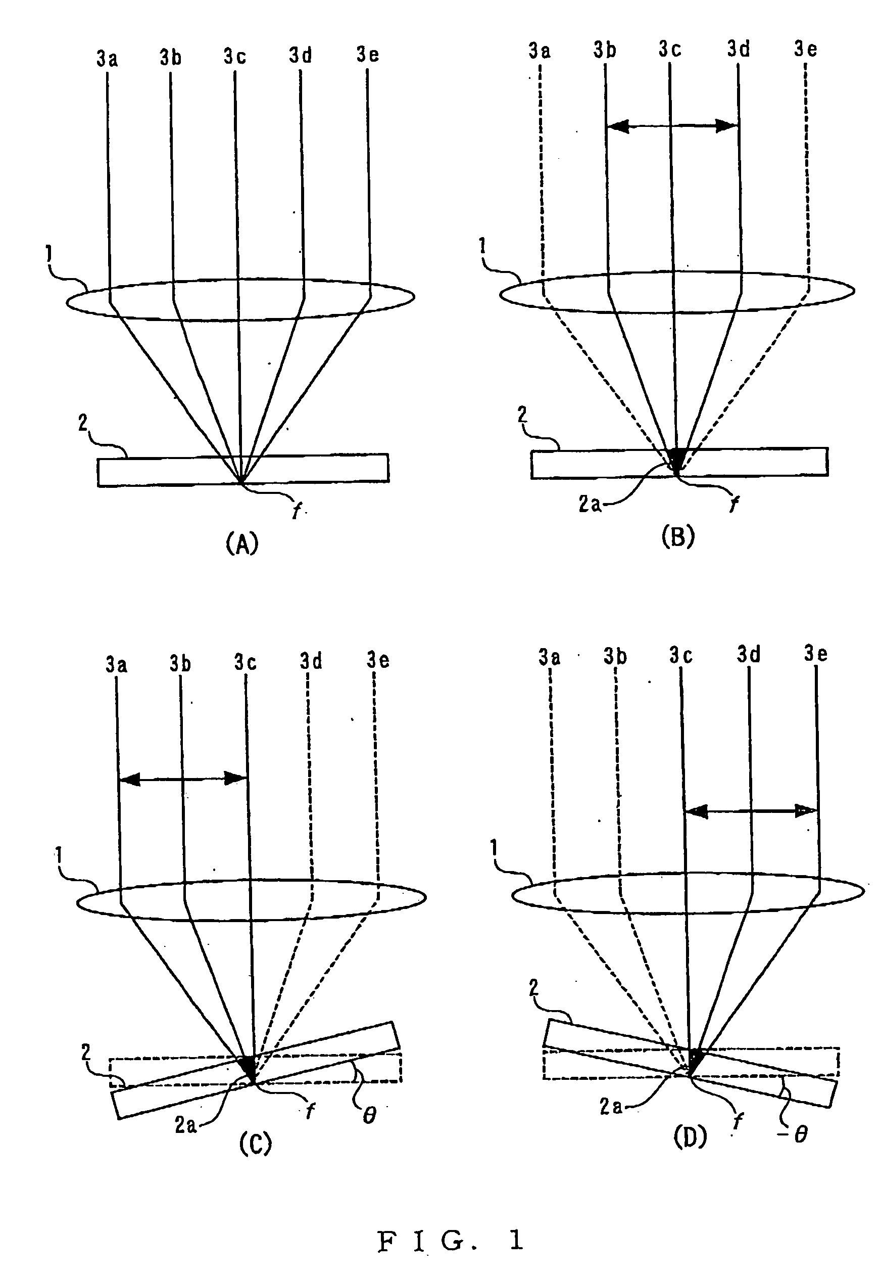
[0046] The basic concept of the present invention will be described by referring to FIG. 1. FIG. 1A to FIG. 1D are illustration showing light rays 3a to 3e as recording light or reproducing light irradiated onto a recording layer of a recording medium by an objective lens 1. As shown in FIG. 1A, parallel light ray flux of the light rays 3a to 3e becomes a convergent light ray flux upon entering the objective lens 1, being converged towards a focal point f in the recording layer 2.

[0047] Looking at this phenomenon from a different point of view, it can be seen that each of the light rays 3a to 3e enters the recording layer 2 of the recording medium at different angles. That is, in FIG. 1A, the light rays 3a and 3b enter the recording layer 2 from the left side, the light ray 3c from the front, and the light rays 3d and 3e from the right side. Therefore, the angle of i...


PUM


Abstract

In an optical information recording/reproducing apparatus using holography in which a relative inclination between a recording light or a reproducing light and a recording medium is corrected by using a device which is suitable for size-reduction. Provided is an optical information recording/reproducing apparatus for recording/reproducing information to/from a recording medium through irradiating recording light or reproducing light by an objective lens onto a recording medium to/from which information is recorded/reproduced using holography, wherein light ray flux of the recording light or the reproducing light entering an objective lens is parallel-translated according to a relative inclination between the recording light or the reproducing light and the recording medium.

Description

BACKGROUND OF THE INVENTION [0001] 1. Field of the Invention [0002] The present invention relates to an apparatus which performs at least either recording or reproduction of information to / from optical information recording medium to which information is recorded using holography. [0003] 2. Description of the Related Art [0004] Conventionally, in holographic recording for recording information onto a recording medium using holography, in general, information light carrying image information and recording-specific reference light overlap with each other in a recording medium and interference pattern generated thereby is written onto the recording medium. For reproducing the recorded information, reproduction-specific reference light is irradiated onto the recording medium so as to reproduce image information by diffraction of the interference pattern (see Japanese Unexamined Patent Publication No. 11-311938). [0005] Recently, for achieving super high density optical recording, volume...

Claims


Application Information

Patent Timeline
IPC IPC(8): G02B5/32G11B7/00G03H1/26G11B7/0065G11B7/095G11B7/125G11B7/128G11B7/135G11B7/1359G11B7/1362G11B7/1365G11B7/1378
CPCG11B7/0065G11B7/0956G11B7/128G11B7/1378G11B7/1362G11B7/1365G11B7/1359
Inventor HORIMAI, HIDEYOSHI
Owner OPTWARE
Why Eureka
Try Eureka