
Noise canceling microphone system and method for designing the same

a microphone and noise canceling technology, applied in the field can solve the problems of degrading the coherence between the two microphone elements, not necessarily working for affecting the performance of active noise canceling microphones, so as to improve the broadband noise canceling performance and improve the system speech transmission

Inactive Publication Date: 2005-02-10
GENTEX CORP
View PDF19 Cites 44 Cited by
  • Summary
  • Abstract
  • Description
  • Claims
  • Application Information

AI Technical Summary

Benefits of technology

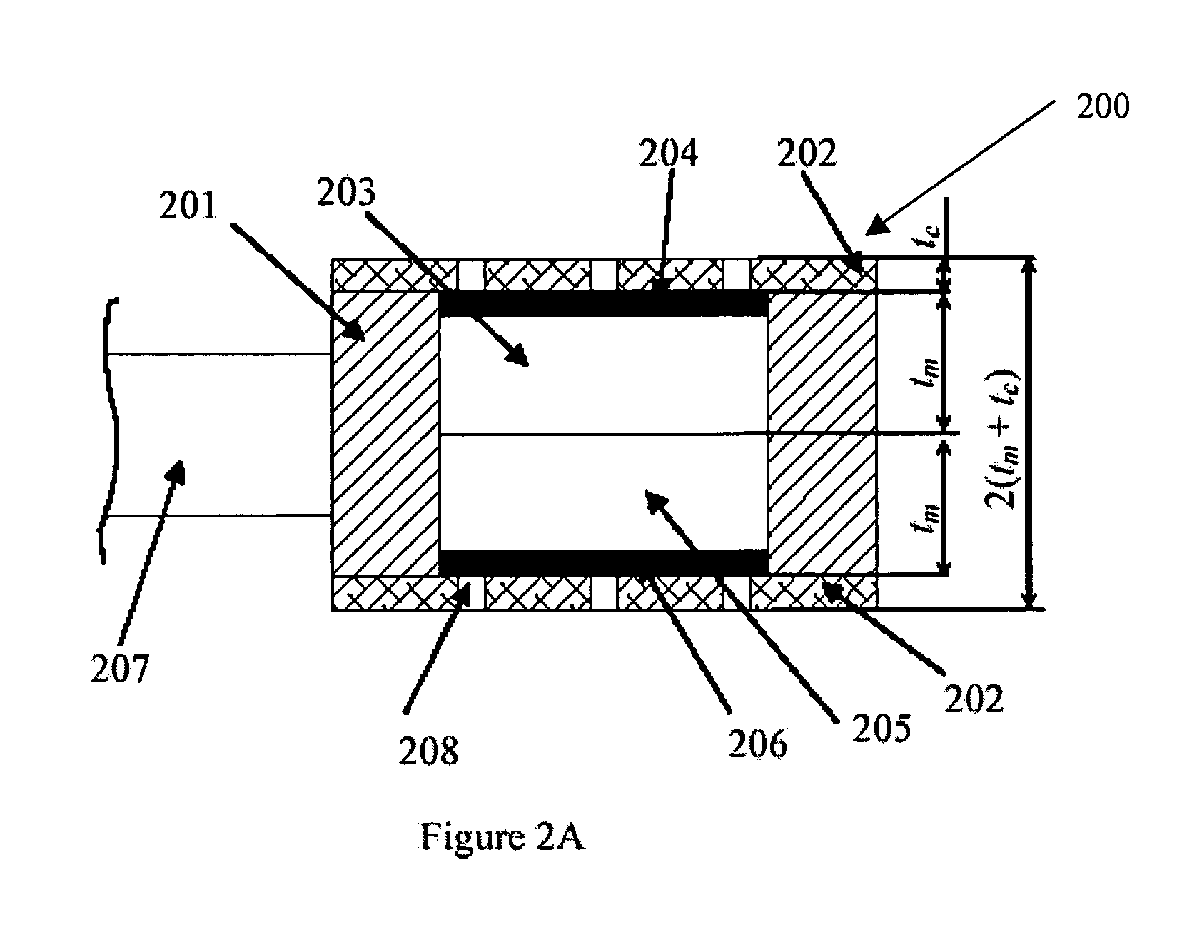
In an embodiment of the present invention, a method for designing a microphone housing improves the broadband noise canceling performance of an active noise canceling microphone system while also ensuring improved speech transmission through the system. Using this method, first and second microphone elements are selected each having a diameter “d” and a thickness “t”. The two microphone elements are aligned axially with the back surfaces in contact and secured in an axially aligned cylindrical cavity within a cylindrically shaped housing. In an alternative embodiment, a single element microphone comprising two diaphragms inside the element and having a thickness of “2t” is used in place of the two microphone elements.
In another embodiment of the present invention, in the event the near field power difference is more than 11 dB, the thickness of the microphone elements “t” and, the thickness of the microphone housing “2t” is reduced.
It is therefore an aspect of the present invention to improve the performance of a dual element noise canceling microphone by employing a design method that constrains the near field power difference of the first microphone signal and the second microphone to a range from 8 dB to 11 dB.
It is yet another aspect of the present invention to provide a cone shaped microphone housing with straight or curved outer surface. The cone shaped outer surface of the housing helps to increase the amplitude difference in near-field, desired speech signal between the two microphone elements used in active noise canceling microphones (described as amplitude difference in the embodiments). This shape also continues to allow excellent far field coherence between the two elements for improved active cancellation.

Problems solved by technology

It does not necessarily work for active noise canceling microphones since the effectiveness of the active element will be highly dependent on the broadband coherence between the two individual microphone elements.
The addition of such a reflector on one side of the microphone housing as described by Tate will inevitably degrade the coherence between the two microphone elements especially at high frequencies.
This may instead result in a degradation of the performance of the active noise canceling microphone.
However, the Sasaki patent does not disclose or teach the effects of the microphone shape and dimensions on the coherence function and the amplitude difference in the desired signal sensed by the two microphone elements.
And furthermore, the configuration of orienting the two microphone elements in the same direction is not a practical choice since such a configuration may result in a more effective speech canceller than a noise canceller.
However, the Andrea patent does not teach a specific size or shape of the acoustic baffle design so that both good noise canceling performance for background noise and a significant differentiation in near-field speech (desired signal) amplitudes between the two microphone elements can be achieved.
In summary, this review of the prior art in housing design and microphone architecture for active noise canceling microphones does not teach the importance of the housing shape and dimensions as these attributes relate to the performance of the active noise canceling microphone.

Method used


Image

  • Noise canceling microphone system and method for designing the same
  • Noise canceling microphone system and method for designing the same
  • Noise canceling microphone system and method for designing the same

Examples


Embodiment Construction

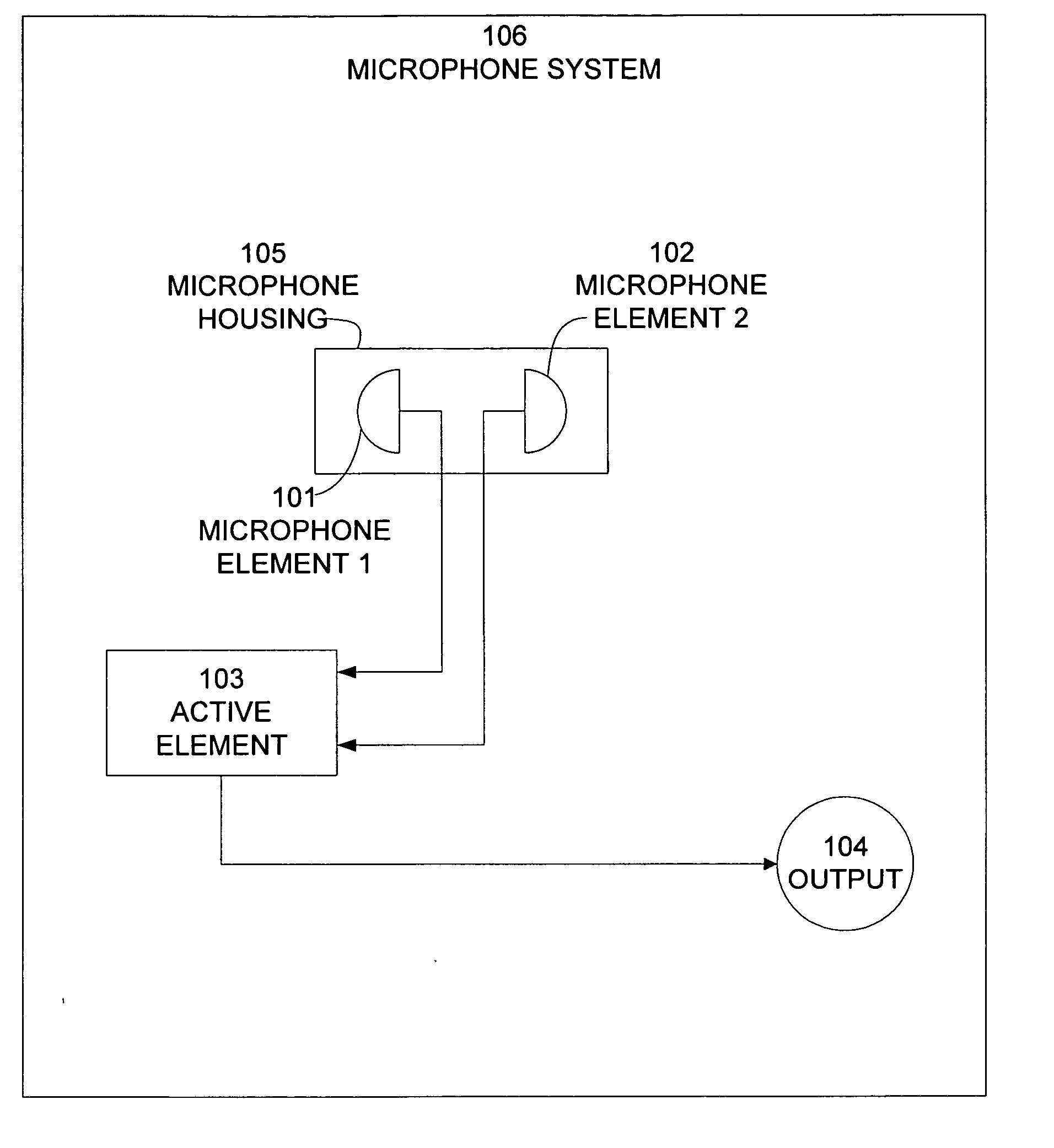
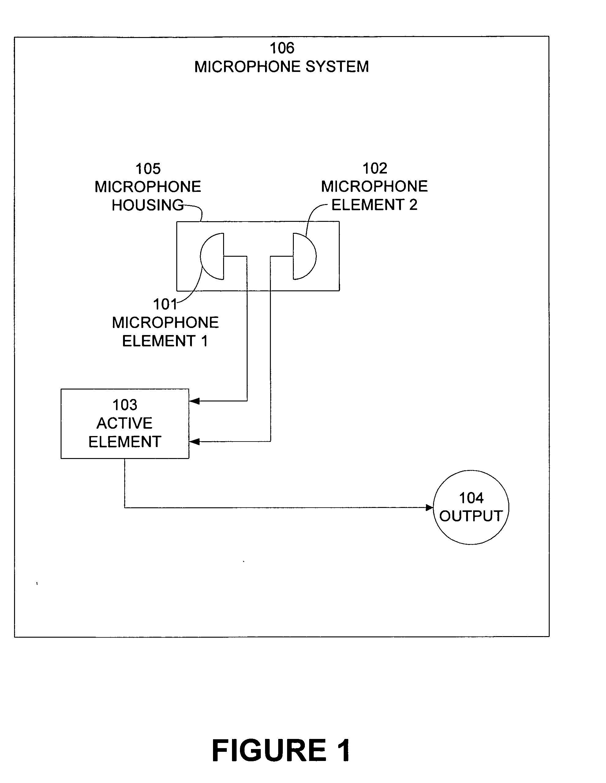
A general block diagram of a noise canceling microphone system according to an embodiment of the present invention is illustrated in FIG. 1. A first microphone element 101 and a second microphone element 102 are enclosed in a microphone housing 105 designed according to embodiments of the present invention. The outputs of first microphone element 101 and second microphone element 102 are connected to an active element 103 having an output terminal 104. The two microphone elements are arranged such that the first element 101 receives the background ambient noise and the desired signal, or the speaker's voice, while the second element 102 receives substantially only the ambient noise. When active element 103 processes the signals from first and second microphone elements (101 and 102) the ambient noise (which as a result of the baffle design of the present invention is essentially equally sensed by the two microphone elements) is cancelled out significantly, leaving a substantial amou...


PUM


Abstract

A microphone housing improves the broadband noise canceling performance of an active noise canceling microphone system while also ensuring improved speech transmission through the system. First and second microphone elements are selected each having a diameter “d” and a thickness “t”. The two microphone elements are aligned axially with the back surfaces in contact and secured in an axially aligned cylindrical cavity within a cylindrically shaped housing. The cylindrically shaped housing has an outside diameter “D,” an interior cavity of diameter of “d,” and a height “2t”. The housing is exposed to an environment comprising both speech and noise. The first microphone element is adapted to receive a signal having both voice and noise components, while the second microphone element is adapted to receive a signal that is predominantly noise. A controller processes signals from the first microphone element and the second microphone element. The values of D and d are selected so to obtain a ratio of D over d between 1 and about 2.4 or a near field power difference of the first microphone signal and the second microphone signal between 8 dB and 11 dB. In the event the near field power difference is more than 11 dB, the outside diameter of the microphone housing “D” is reduced. In the event the near field power difference is less than 8 dB, the outside diameter of the microphone housing “D” is increased.

Description

BACKGROUND The present invention pertains generally to active noise canceling microphones and related devices. More particularly, the present invention relates to a method for designing an acoustically motivated housing and architecture for an active noise canceling microphone comprising two microphone elements, an analog or digital or hybrid (analog and digital) control circuitry and associated control codes or software. The new acoustic housing design method provides improved background noise canceling and enhanced speech intelligibility for such an active noise canceling microphone system as described herein. The performance improvement is realized due to the optimal acoustic design of the shape and dimensions of the microphone housing and the unique assembly method of the microphone elements inside the housing. Noise canceling microphones are widely used in commercial, industry, and military applications where clear communication in noisy ambient environments is required. Ther...

Claims


Application Information

Patent Timeline
Patent Type & Authority Applications(United States)
IPC IPC(8): H04R3/00
CPCH04R2410/05H04R3/005
Inventor DU, YUVAUDREY, MICHAEL A.
Owner GENTEX CORP
Learn More