Methods and apparatus for inspection of lines embedded in highly textured material

a technology of highly textured materials and inspection methods, applied in the field of systems and methods for locating lines, can solve the problems of inability to meet the needs of industrial inspection, inability to detect features, and complex programs, and achieve the effects of improving the ability of such machines, facilitating flexible precision industrial inspection, and improving the ease of programming of such systems

Inactive Publication Date: 2005-02-10
MITUTOYO CORP
View PDF1 Cites 78 Cited by
  • Summary
  • Abstract
  • Description
  • Claims
  • Application Information

AI Technical Summary

Benefits of technology

[0010] The above-described machine vision inspection systems provide advantages, such as automated video inspection. However, in a variety of applications, it would be desirable to improve the ability of such machines to locate lines that have known relative orientations, such as, for example, parallel lines, that are embedded in, and/or superimposed on, highly-textured and/or low-contrast material without needing extensive machine operator intervention or complicated programming by the machine operator. Furthermore, in contrast to solutions developed for so called “on-line” or “in-line” machine vision inspection systems, for precision “off-line” or “near-line” machine vision inspection systems that are generally designed to facilitate flexible prec...

Problems solved by technology

Due to the low-contrast and “noisy” nature of an image of a highly-textured and/or low-contrast material having such features, the systems and methods of conventional machine vision systems used to detect such features either have lacked precision, have been complex to program, have been unreliable in operation, and/or have been slow to execute.
Accordingly, the specific problems associated with providing a relatively si...

Method used


Image

  • Methods and apparatus for inspection of lines embedded in highly textured material
  • Methods and apparatus for inspection of lines embedded in highly textured material
  • Methods and apparatus for inspection of lines embedded in highly textured material

Examples


Embodiment Construction

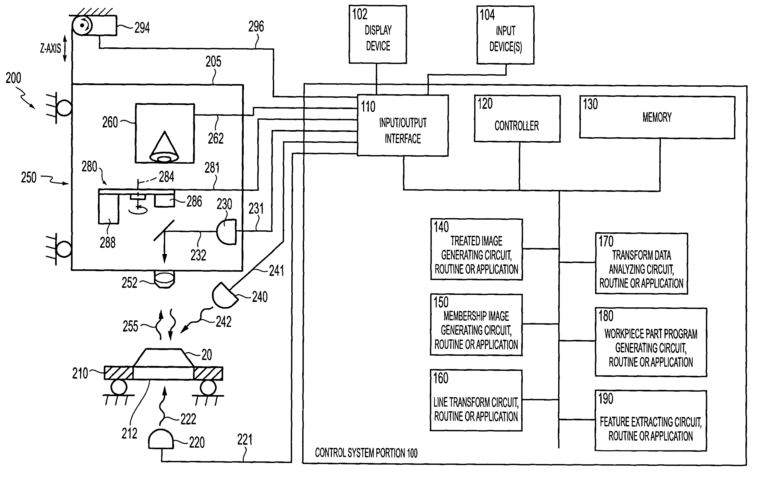
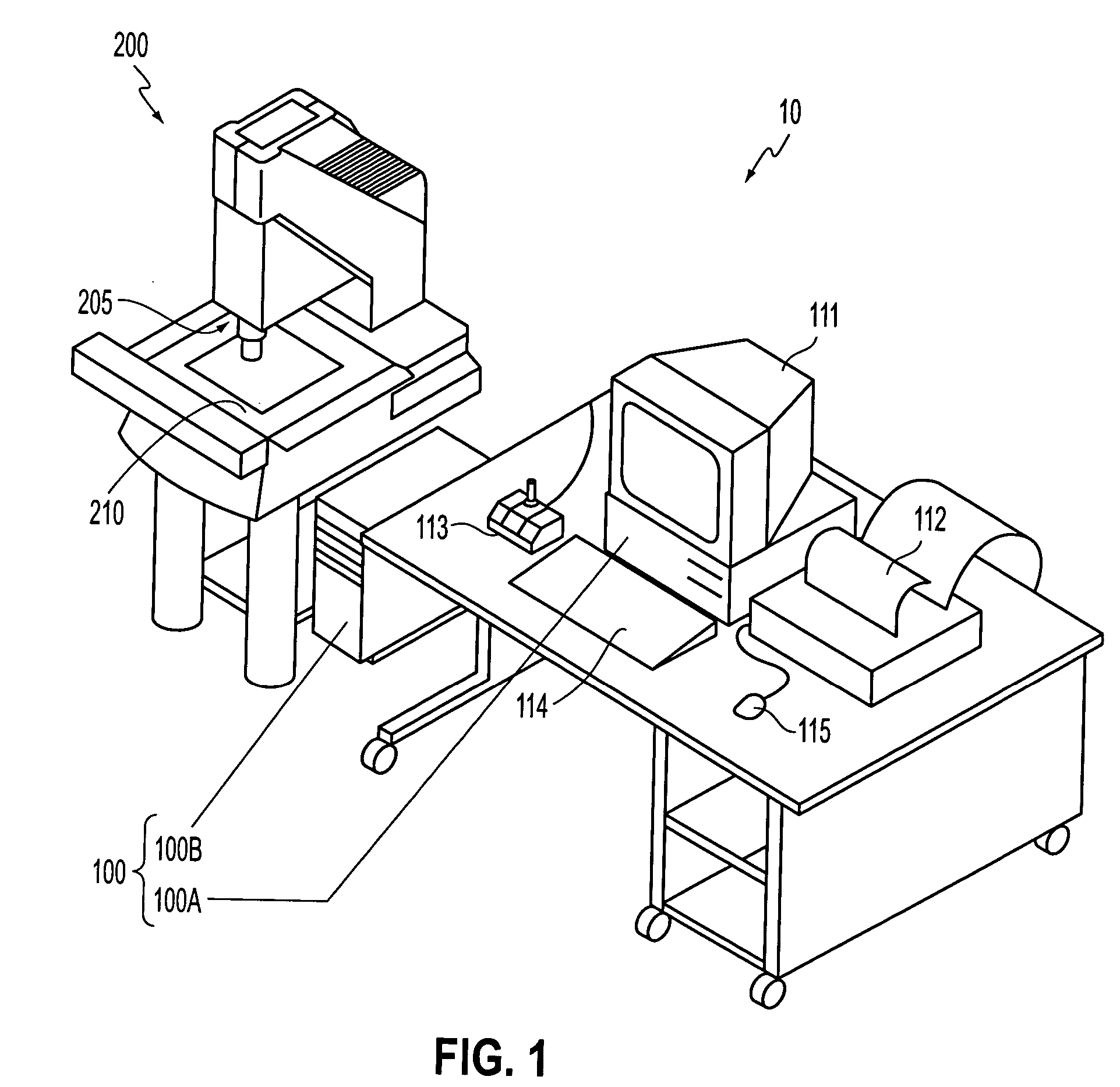
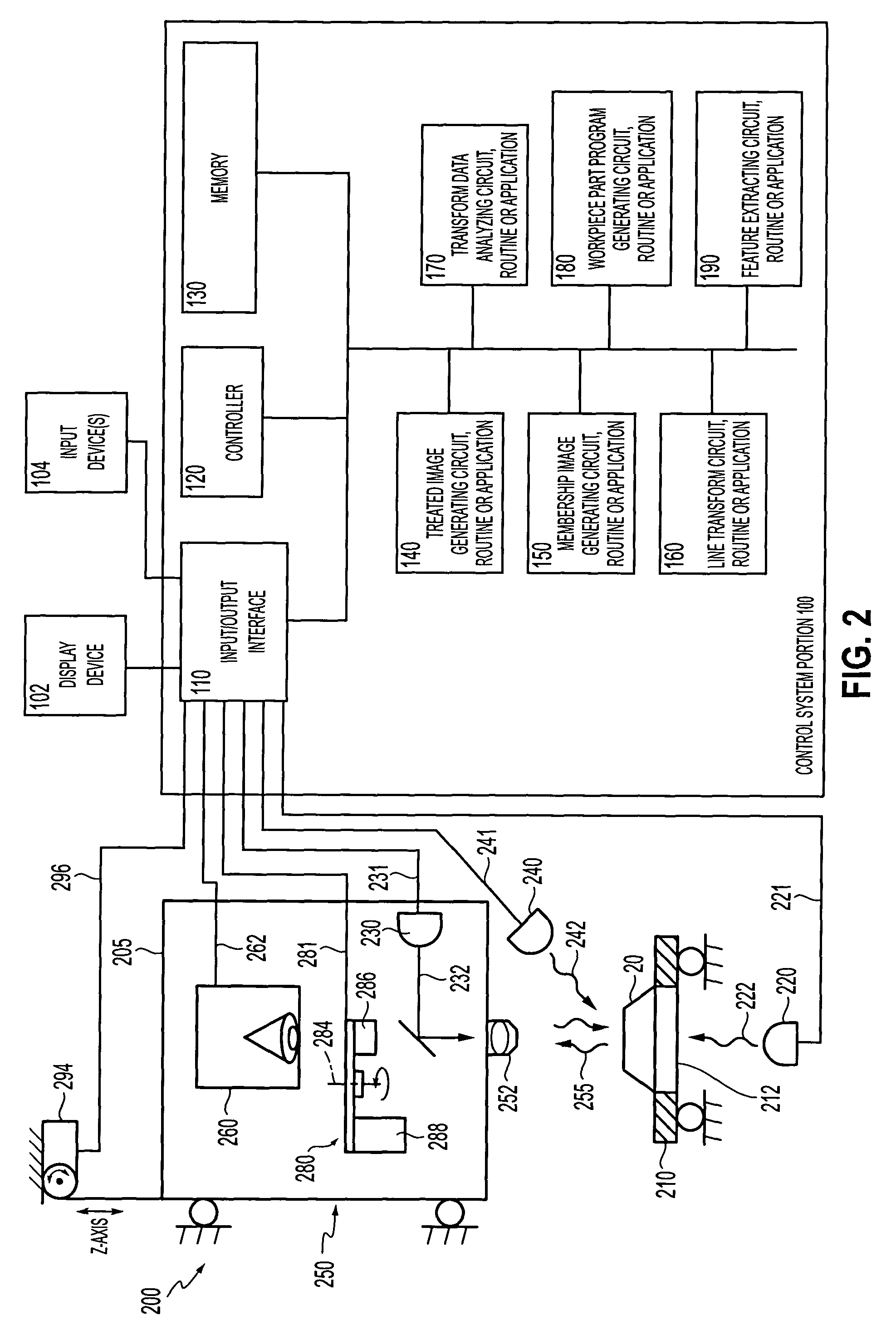
[0042]FIG. 1 is a block diagram of one exemplary embodiment of a general purpose programmable machine vision inspection system 10 in accordance with this invention. The machine vision inspection system 10 includes a vision measuring machine 200 that is operably connected to exchange data and control signals with a control system 100. The control system 100 is further operably connected to exchange data and control signals with one or more of a monitor 111, a printer 112, a joystick 113, a keyboard 114, and / or a mouse 115. The vision measuring machine 200 includes a moveable workpiece stage 210 and an optical imaging system 205 which may include a zoom lens or a number of interchangeable lenses. The zoom lens or interchangeable lenses generally provide various magnifications for the images provided by the optical imaging system 205.

[0043] The joystick 113 can typically be used to control the movement of the movable workpiece stage 210 in both the X and Y directions, which are genera...


PUM


Abstract

A machine vision inspection system is programmed and operated to identify one or more lines appearing in a highly-textured and/or low-contrast surface of a workpiece. In a learning mode, a line-enhancing image is generated from a captured image of the workpiece. In various embodiments, the enhanced image is based on a previously determined technique governed by a selected value for an associated parameter. A line transform is used to transform the enhanced image. The transformed data is analyzed to identify local extrema corresponding to the lines to be identified. Part program instructions are created to automatically generate the line-enhancing image, to transform it, and to analyze the transformed data set to identify the lines to be detected. Line constraint(s) that characterize a consistent line arrangement are used to improve the speed and reliability of the line detection.

Description

BACKGROUND OF THE INVENTION [0001] 1. Field of Invention [0002] The invention relates systems and methods for locating lines, having known relative orientations, that are embedded in a highly-textured and / or low-contrast material. [0003] 2. Description of Related Art [0004] Precision machine vision inspection systems can be used to obtain precise dimensional measurements of inspected objects and to inspect various other object characteristics. Such systems may include a computer, a camera and optical system and a precision stage that is movable in multiple directions to allow the camera to scan the features of a workpiece that is being inspected. One exemplary prior art system that is commercially available is the QUICK VISION™ series of vision inspection machines and QVPAK™ software available from Mitutoyo America Corporation (MAC), located in Aurora, Ill. The features and operation of the QUICK VISION™ series of vision inspection machines, and the QVPAK™ software are generally des...

Claims


Application Information

Patent Timeline
IPC IPC(8): G06T1/00G01B11/24G06T5/00G06T5/10G06T7/00G06T7/60G06V10/48
CPCG06K9/4633G06T7/0006G06T2207/10016G06T7/0095G06T2207/30164G06T7/0085G06T2207/30124G06T7/13G06T7/168G06V10/48
Inventor VENKATACHALAM, VIDYA
Owner MITUTOYO CORP
Why Eureka
Try Eureka