Parallel fiber-fan-out optical interconnect for fiber optic system

a fiber optic system and fiber optic technology, applied in the field of fiber optic technology, can solve the problems of reducing yield, time-consuming and expensive individual handling of fibers, and requiring the dumping of the entire osa

Inactive Publication Date: 2005-02-10
AGILENT TECH INC
View PDF6 Cites 6 Cited by
  • Summary
  • Abstract
  • Description
  • Claims
  • Application Information

AI Technical Summary

Problems solved by technology

This approach has the disadvantage that if a single channel in the OSA is found to be defective during assembly or testing, the entire OSA must be discarded, reducing yield.
This approach has the further disadvantage that similar products that use different numbers of channels, including single channel products, must each use a different OSA.
This approach has the disadvantage that the individual handling of the fibers is time consuming and expensive and sometimes requires that the optical fibers have additional length that undesirably increases the length and width of this second type of parallel optical module.

Method used


Image

  • Parallel fiber-fan-out optical interconnect for fiber optic system
  • Parallel fiber-fan-out optical interconnect for fiber optic system
  • Parallel fiber-fan-out optical interconnect for fiber optic system

Examples


first embodiment

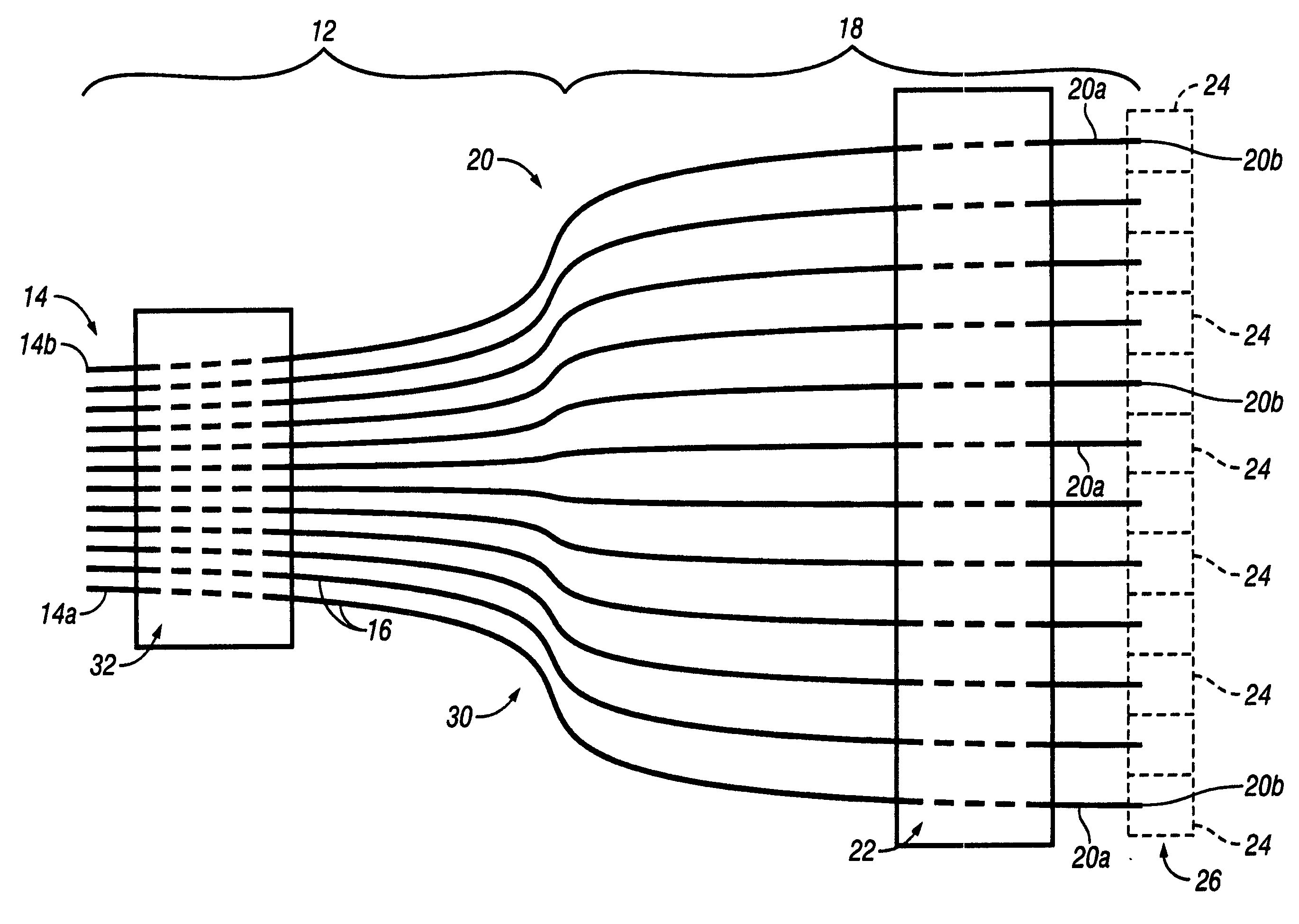
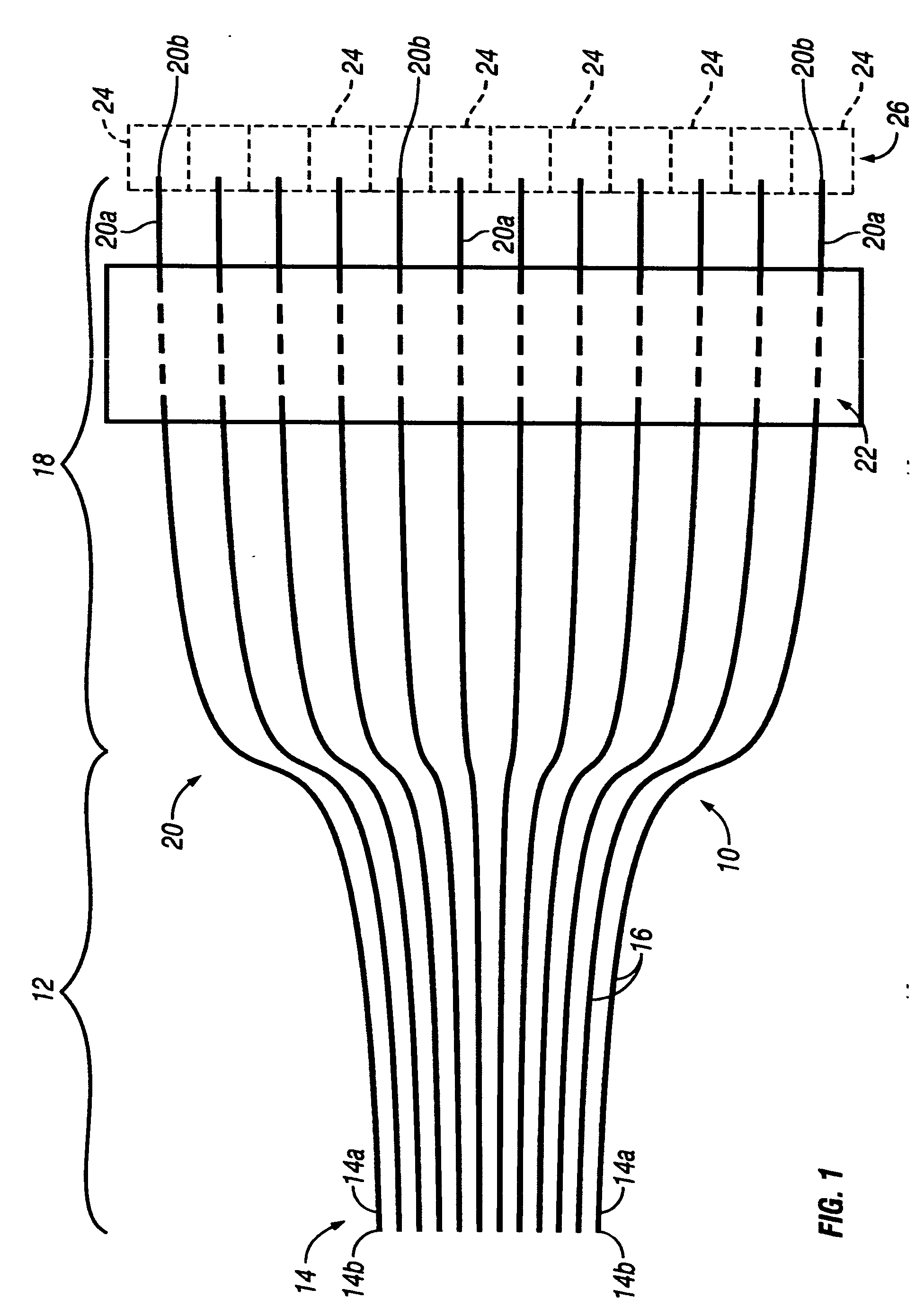
[0016] Referring to FIG. 1, a parallel fiber-fan-out (FFO) optical interconnect 10 in accordance with the present invention has a fiber ribbon 12 including a plurality of first segments 14 of optical fibers 16 extending longitudinally in a planar side-by-side arrangement having a first predetermined pitch, such as two-hundred and fifty micro-meters. The optical fibers 16 could be either plastic optical fiber (POF) or glass optical fiber (GOF). Clearly the center-to-center spacing or pitch is much greater where the optical interconnect is designed for POF than where it is designed for GOF. A fiber-fan-out 18 including a plurality of second segments 20 of the optical fibers 16 extends in a diverging arrangement from the fiber ribbon 12. The first segment 14 and the second segment 20 of each optical fiber 16 are sections or lengths of the same continuous uninterrupted optical fiber. A generally rectangular fiber holder 22 made of molded plastic extends transversely across the plurality...

second embodiment

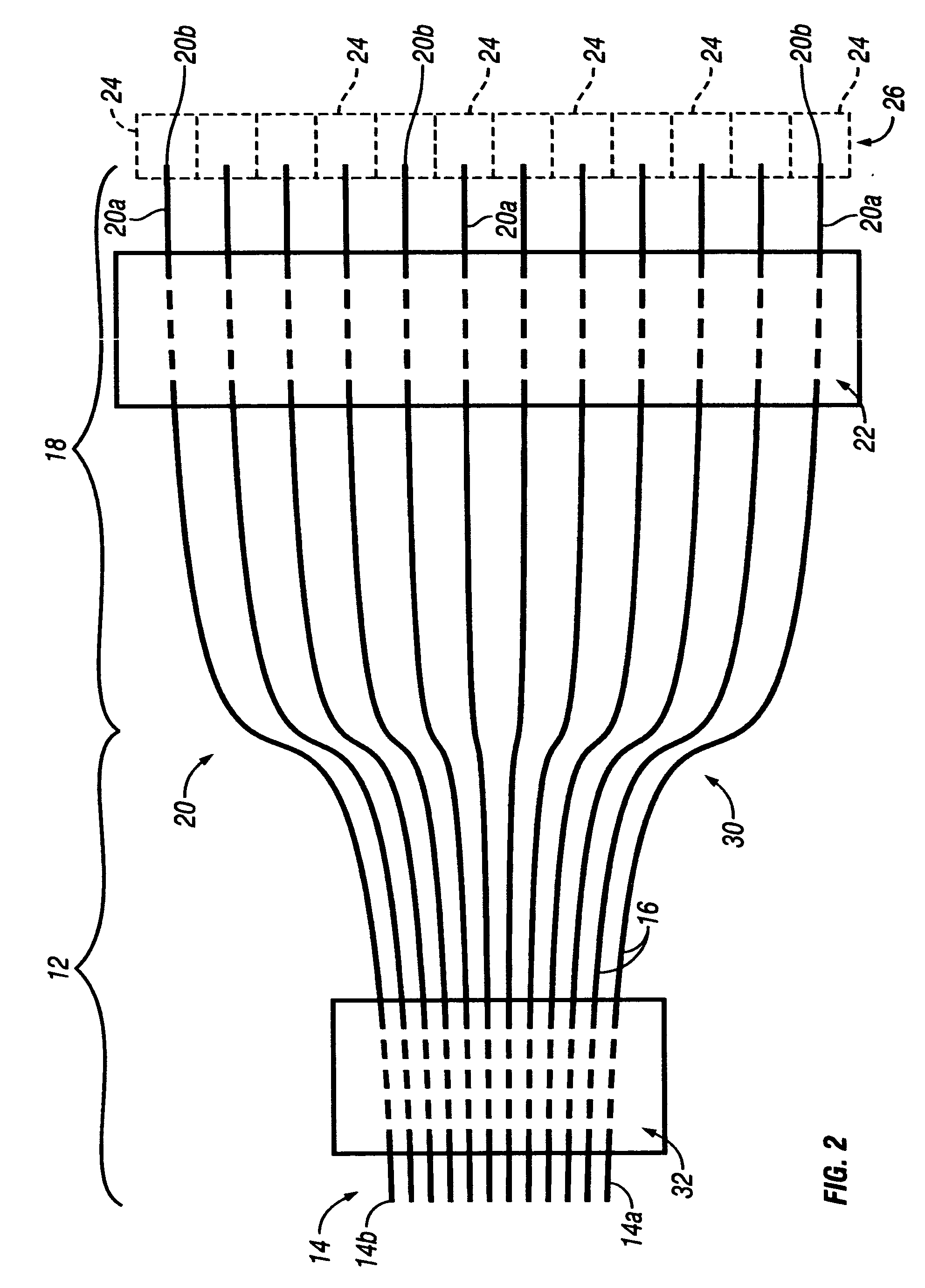
[0021]FIG. 2 illustrates a parallel fiber-fan-out optical interconnect 30 in accordance with the present invention. The optical interconnect 30 is similar to the optical interconnect 10 except that the former has a second generally rectangular fiber holder 32. The fiber holder 32 is a separate discrete body member that maintains the terminal portions 14a of the first segments 14 of the optical fibers 16 in the first predetermined pitch instead of the ribbonizing or web material of the fiber ribbon 12 which is not part of the optical interconnect 30. In FIG. 2, the intermediate portions of the first segments 14 of the optical fibers 16 that pass through the second fiber holder 32 are shown in broken lines to indicate that they are concealed. The second fiber holder 32 can be formed in any of the fashions described above in connection with the first fiber holder 22, i.e. with the optical fibers 16 either being inserted through pre-formed holes, clamped around, molded over, and optiona...

third embodiment

[0022]FIG. 3 illustrates a parallel fiber-fan-out optical interconnect 40 in accordance with the present invention. A common injection molded plastic housing assembly 42 illustrated in phantom lines surrounds the first segments 14 and the second segments 20 of the optical fibers 16 except for their terminal portions 14a and 20a, respectively. The housing assembly 42 may have flat opposing flat faces with stepped side edges similar to the configuration of multi-pin electrical connectors that are plugged into personal computers. The housing assembly 42 holds the terminal portions 14a in the first predetermined pitch and the terminal portions 20a in the second predetermined pitch. Thus the cleaved ends 14b of the first segments 14 can be mated with the corresponding ends of the routed optical fibers held in the mating conventional parallel fiber connector (not illustrated). It also allows the cleaved ends 20b of the terminal portions 20a of the second segments 20 to be mated with the O...


PUM


Abstract

A fiber ribbon includes a plurality of first segments of optical fibers that extend in a planar side-by-side arrangement having a first predetermined pitch. A fiber-fan-out including a plurality of second segments of the optical fibers extends in a diverging arrangement from the fiber ribbon. A fiber holder extends across the plurality of second segments of the optical fibers for maintaining a plurality of terminal portions of the second segments in a second predetermined pitch that is greater than the first predetermined pitch so that the terminal portions can each be optically coupled to a corresponding optical subassembly (OSA) of a plurality of OSAs arranged in a linear array. An alternate embodiment uses a second fiber holder in place of the fiber ribbon. The holders can be replaced with a common housing assembly spanning all but the terminal portions of the optical fibers.

Description

FIELD OF THE INVENTION [0001] The present invention relates to fiber optic technology, and more particularly, to multi-channel interconnect devices that connect a plurality of parallel optical fibers with optical subassemblies including emitters or detectors. BACKGROUND OF THE INVENTION [0002] Fiber optic systems are used to reliably send large amounts of data over both short and long haul routes and often employ parallel communications modules comprising a 1×N array of optoelectronic devices (OEs), either photoemitters, such LEDs or laser diodes, or photodetectors such as PIN photodiodes, integrated detector / preamplifiers (IDPs), or avalanche photo-diodes (APDs). [0003] There are two conventional types of parallel optical module. The most common type employs a single optical subassembly (OSA) that incorporates multiple OEs (photoemitters or photodetectors) that are matched in number to the number of fibers in the connector. This approach has the disadvantage that if a single channe...

Claims


Application Information

Patent Timeline
Patent Type & Authority Applications(United States)
IPC IPC(8): G02B6/42G02B6/04G02B6/44
CPCG02B6/4471G02B6/4249
Inventor LEMOFF, BRIAN E.
Owner AGILENT TECH INC
Why Eureka
Try Eureka