Device, system and method for on-line monitoring of flow quantities

a flow quantity and flow control technology, applied in the direction of engines, machines/engines, instruments, etc., can solve the problems of affecting the operation of the process system, increasing the risk of changing or disturbing the actual flow in an unfavorable manner, and exposing the sensors to wear and potential damag

Inactive Publication Date: 2005-02-10
ABB (SCHWEIZ) AG
View PDF7 Cites 57 Cited by
  • Summary
  • Abstract
  • Description
  • Claims
  • Application Information

AI Technical Summary

Benefits of technology

It is thus a general object of the present invention to provide devices and methods for improving monitoring, control and diagnosing of systems involving a fluid flow. A further object of the present invention is to provide devices and methods, which allow for on-line measurements of flow quantities. Another further object is to provide such devices, which are cheaper than the prior art solutions. Another object is also to provide devices and methods, which are easily integrated into existing equipment, such as frequency converters or soft starters of pump or fan motors.
Further advantages are that there is no need for installing any sensors directly in or on the flow path, which makes installation, substitution or repair possible without interrupting the flow. However, the measurements and calculations of the requested quantities are performed in the direct vicinity of the flow path, which makes the method possible to apply for controlling purposes. No time-consuming off-line analyses have to be performed.

Problems solved by technology

Hence, in such system and systems of a similar design, a number of sensors have to be introduced into the flow, which always exposes the sensors to wear and potential damage.
Furthermore, sensors introduced in-line also increase the risk for changing or disturbing the actual flow in an unfavourable manner.
Replacement or repair of such sensors will typically cause an operation stop of the process system, which often is very costly.
Also the sensors themselves are relatively costly.
There are thus a number of disadvantages with flow measurements according to prior art.
A problem with the devices disclosed in U.S. Pat. No. 4,781,525 is that a separate rotational speed sensor has to be provided, which is both expensive and in many cases also difficult to provide for mechanical reasons.

Method used


Image

  • Device, system and method for on-line monitoring of flow quantities
  • Device, system and method for on-line monitoring of flow quantities
  • Device, system and method for on-line monitoring of flow quantities

Examples


Embodiment Construction

The potential application areas of the present invention are covering a wide range of technical fields. Non-excluding examples are e.g. water transport, food industry, pulp manufacturing, slurry pumping, oil and gas transport, chemical industry and ventilation systems. Anyone skilled in the art easily understands that the list of possible applications can be made far more extensive.

The present invention can be utilised in systems where a fan, pump or other flow-creating device causes a flow of fluid or pressure rise. Preferable embodiments involve such flow-creating devices driven by electric motors.

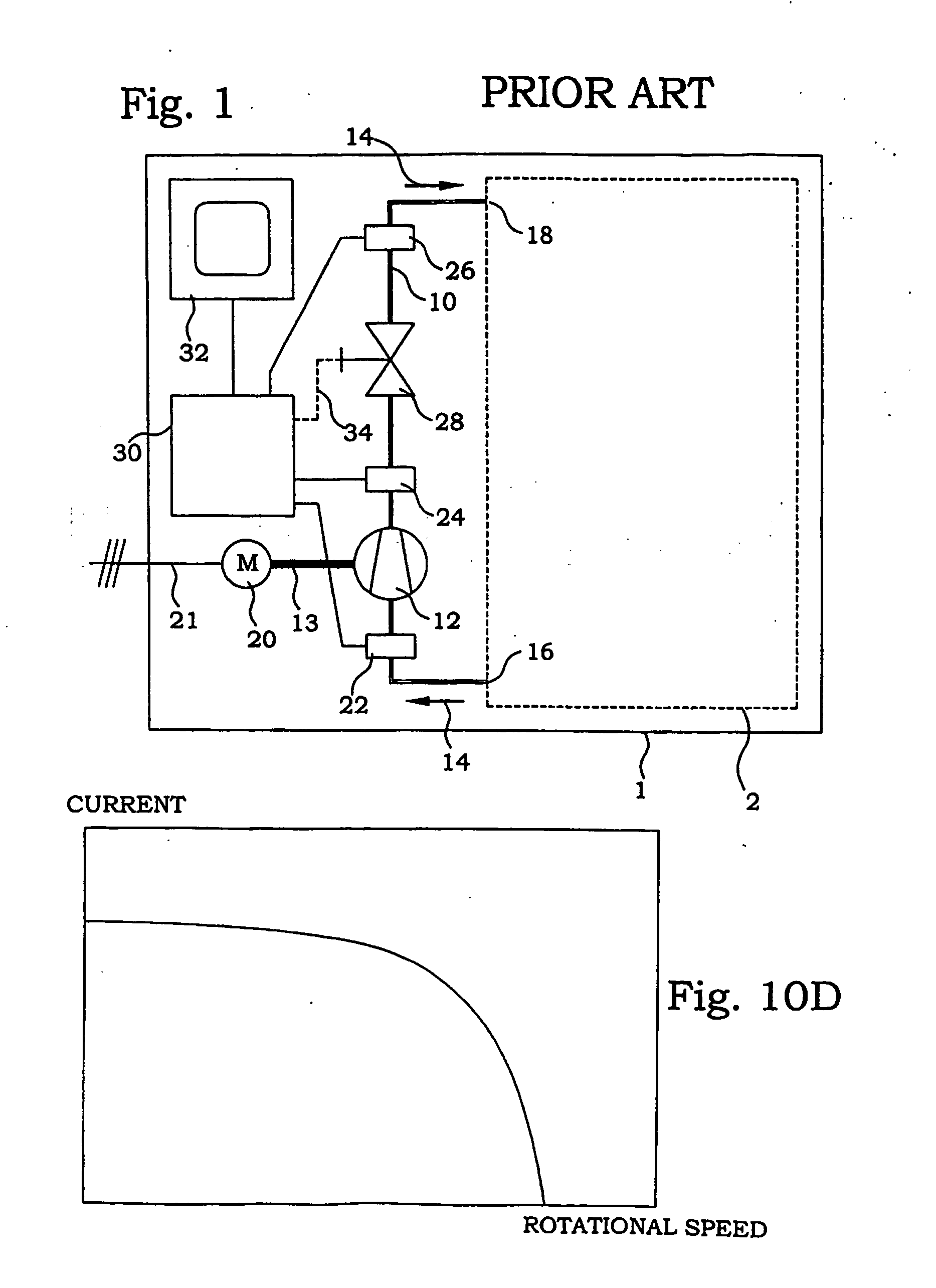
In order to illustrate the benefits of the present invention, this description starts with a brief description of a typical system according to prior art, illustrated in FIG. 1. A flow system 1 comprises a flow path 10 of a fluid, e.g. a liquid, a gas, a mixture of gases, a mixture of liquids, a mixture of gases, liquids and solids, an emulsion, a slurry, a suspension etc. A flow-cr...


PUM


Abstract

Measures of a torque and rotational speed of a pump or fan are obtained, from which a mechanical input power can be calculated. By further using predetermined relations between mechanical input power and flow rate through the pump or fan, a measure of the flow rate can be derived without use of in-line flow or pressure sensors. In preferred embodiments the torque and / or rotational speed is obtained by measuring the input current and voltage of a motor driving the pump or fan and using predetermined relations between on the one hand current and voltage and on the other hand torque and rotational speed. Furthermore, also other flow properties, such as pump head, pump efficiency and total efficiency can be determined in this manner.

Description

TECHNICAL FIELD The present invention relates to monitoring and control of flow quantities in association with pumps or fans. BACKGROUND Many process systems of today include flows of different fluids, where the flow is created by a fan or pump. In many cases, the flow rate and other quantities related to the flow are of crucial importance or at least of interest for controlling the process. The measured flow and related quantities are typically used as input parameters in monitoring, measuring and / or controlling processes. There is thus a general request in many process systems involving fluid flows for measuring flows and pressures caused by different flow-creating means, i.e. essentially fans and pumps. The straightforward approach used in prior art employs the use of direct measurements of flow-related quantities. In DE 198 51 795 A1, a system and a method for textile treatment are disclosed. A respective pressure sensor is introduced within a flow line of treatment fluid imm...

Claims


Application Information

Patent Timeline
Patent Type & Authority Applications(United States)
IPC IPC(8): G01F1/80
CPCF04D15/0088G01F1/80F04D27/001
Inventor OHLSSON, BERTILWINDECKER, ULRIKEZAHRAI, SAID
Owner ABB (SCHWEIZ) AG
Why Eureka
Try Eureka