Method and magnetic resonance tomography apparatus for correcting changes in the basic magnetic field

Active Publication Date: 2005-02-10
SIEMENS HEATHCARE GMBH
View PDF5 Cites 27 Cited by
  • Summary
  • Abstract
  • Description
  • Claims
  • Application Information

AI Technical Summary

Benefits of technology

An object of the present invention is to provide a method with which, in a simple manner and for every MRT apparatus, in particular for functional, contrast agent-aided and diffusion measurement methods, durin

Problems solved by technology

In addition to this, interferences of local field inhomogeneities increase with increasing readout time.
Given the combination of EPI with contrast agent-supported methods (perfusion imaging), however, these effects can be corrected only with difficulty because the successive images are very different due to the contrast agent bolus flowing therethrough.
This can lead to errors or given a low residual signal in the images, to outright impossibility of the image analysis.
A similar problem occurs in diffusion imaging.
The data of a single acquisition are unusable for a correction due to the high noise portion.
If, for example, the B0 field now changes during the diffusion measurement, the individual acquisitions are displaced relative to one another, and the resulting image quality can be impaired.
Moreover, not only are temporal changes of the B0 field problematic, but also the variation of the absolute value of B0 across the sample or the patient to be examined.
In the case of echo planar imaging, this in turn leads to an apparent displacement of the measurement subject, meaning the planned or calculated image position (slice position) is typically incorrect by a few millimeters (up to centimeters).
Pro

Method used


Image

  • Method and magnetic resonance tomography apparatus for correcting changes in the basic magnetic field
  • Method and magnetic resonance tomography apparatus for correcting changes in the basic magnetic field
  • Method and magnetic resonance tomography apparatus for correcting changes in the basic magnetic field

Examples


Embodiment Construction

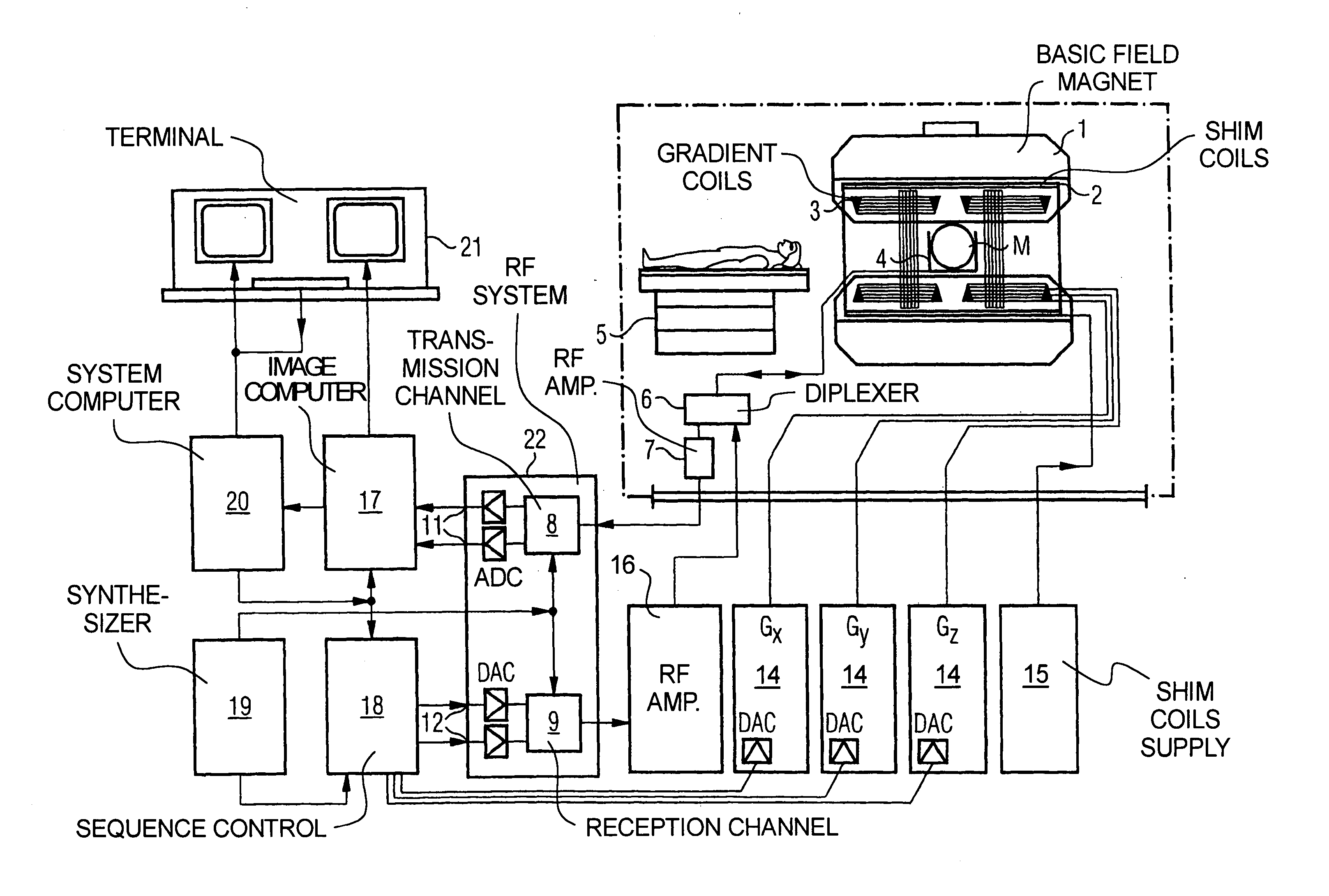
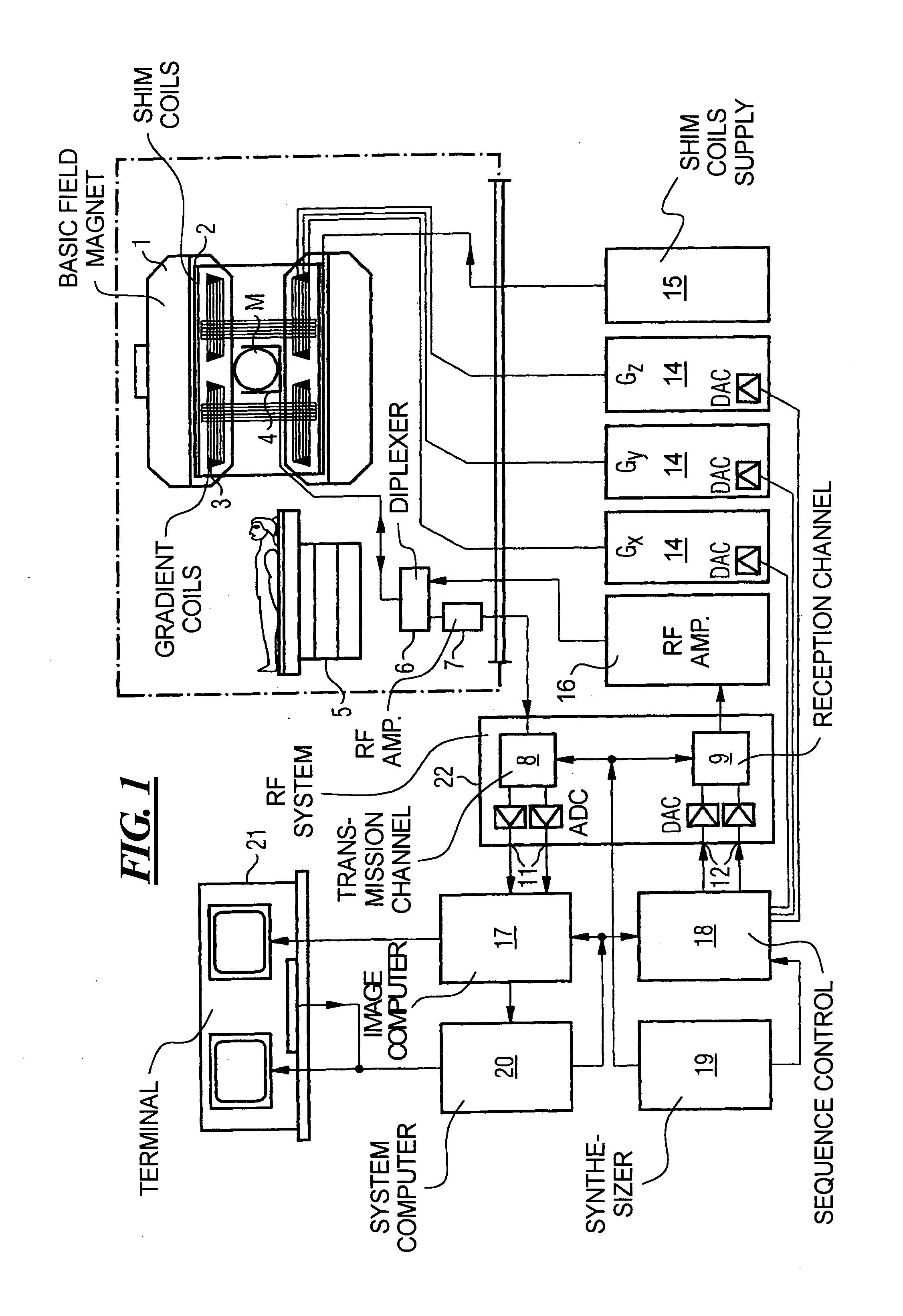
FIG. 1 is a schematic representation of a magnetic resonance tomography apparatus operable pulses according to the present invention. The design of the nuclear magnetic resonance tomography apparatus corresponds to the design of a conventional tomography apparatus, with the differences described below. A basic field magnet 1 generates a temporally constant strong magnetic field B0 to polarize or align the nuclear spins in the examination region of a subject such as, for example, a part of a human body to be examined. The high homogeneity of the basic field magnet required for the magnetic resonance measurement is defined in a spherical measurement volume M into which the parts of the human body to be examined are inserted. To support the homogeneity requirements, and in particular to eliminate temporally invariable influences, shim plates made of ferromagnetic material are mounted at appropriate locations. Temporally variable influences are eliminated by shim coils 2 that are contro...


PUM


Abstract

In a method for calculating a one-dimensional map of the base magnetic field B0 and subsequent correction, based on this map, of image artifacts due to B0 field changes, in the examination of a subject with a magnetic resonance tomography apparatus, data for a slice of the subject to be examined are obtained with a sequence of a fast MRT imaging method that includes at least three phase correction scans and measurement signals of the respective phase correction scans as well as of the slice are obtained, the phase difference of the data points (respectively pertaining to one another) of two phase correction scans, in the form of the acquired measurement signals of the respective phase correction scans, are calculated point-by-point, the average phase difference between the phase correction scans is evaluated, and the frequency offset between the actual resonance frequency relative to the adjusted resonance frequency is calculated based on the average phase difference and the echo time difference between the phase correction scans used, a B0 field map is calculated dependent on the frequency offset and, the measurement data for the slice are corrected using the calculated B0 field map.

Description

BACKGROUND OF THE INVENTION 1. Field of the Invention The present invention generally concerns magnetic resonance tomography (MRT) as employed in medicine for the examination of patients. The present invention is in particular concerned with a method for determination of the B0 (basic magnetic) field, in particular given the use of fast MRT imaging methods such as, for example, TSE, EPI, SSEPI. A projection obtained of the B0 field (B0 field map) of the acquired slice enables the correction of image artifacts arising due to changes in the B0 field. 2. Description of the Prior Art MRT is based on the physical phenomenon of nuclear magnetic resonance and has been successfully used as an imaging method in medicine and biophysics for over 15 years. In this examination method, the subject is exposed to a strong, constant magnetic field. The nuclear spins of the atoms of the subject, which were previously oriented randomly, thereby align. Radio-frequency energy can now excite these “o...

Claims


Application Information

Patent Timeline
IPC IPC(8): G01R33/565
CPCG01R33/243G01R33/56581G01R33/56563
Inventor KRUGER, GUNNARTHESEN, STEFAN
Owner SIEMENS HEATHCARE GMBH
Why Eureka
Try Eureka