
Device and method for staged implantation of a graft for vascular repair

a vascular repair and staged graft technology, applied in the field of intraluminal grafts, can solve the problems of increasing the risk of rupture and hemorrhagic death, the most life-threatening of aneurysms, and the risk of direct surgical intervention of this magnitude, and achieve the effect of facilitating the delivery of the gra

Inactive Publication Date: 2005-02-10
COOK INC
View PDF60 Cites 18 Cited by
  • Summary
  • Abstract
  • Description
  • Claims
  • Application Information

AI Technical Summary

Benefits of technology

This approach reduces the diameter of the delivery capsule, enhances flexibility, and enables direct percutaneous insertion, reducing complications and allowing for minimally invasive procedures that can be performed by a wider range of medical personnel, potentially as an outpatient procedure.

Problems solved by technology

One of the most common, and among the most life threatening, is an aneurysm of the abdominal aorta between the renal and iliac arteries.
If untreated, the aneurysm dilates progressively with an ever increasing risk of rupture and hemorrhagic death.
The risks involved in direct surgical intervention of this magnitude are great, and include an extensive recovery period.
However, the use of generally cylindrical grafts to reinforce vascular walls in a patient is not without problems.
One of the problems encountered in the art of delivering grafts to the vascular system of a patient is that complications may be encountered in maneuvering the compressed graft and its delivery system around the bends and branches of the patient's vascular system.
It will be appreciated that the greater the outer dimension of the capsule containing the compressed graft to be delivered, the more inflexible it will be, making delivery to the final destination more difficult and perhaps even impossible in some patients.
Another problem encountered in the art of graft delivery is that, in the majority of cases, the patient must be subject to surgery in which the appropriate vessel is surgically exposed and opened by incision to allow entry of the graft.
Significantly, it is this surgical procedure on the vessel which gives rise to the most serious complications known in the art of minimally invasive graft delivery, with complications taking the form of infection, patient discomfort, and necrosis of the vessel itself.

Method used


Image

  • Device and method for staged implantation of a graft for vascular repair
  • Device and method for staged implantation of a graft for vascular repair
  • Device and method for staged implantation of a graft for vascular repair

Examples


Embodiment Construction

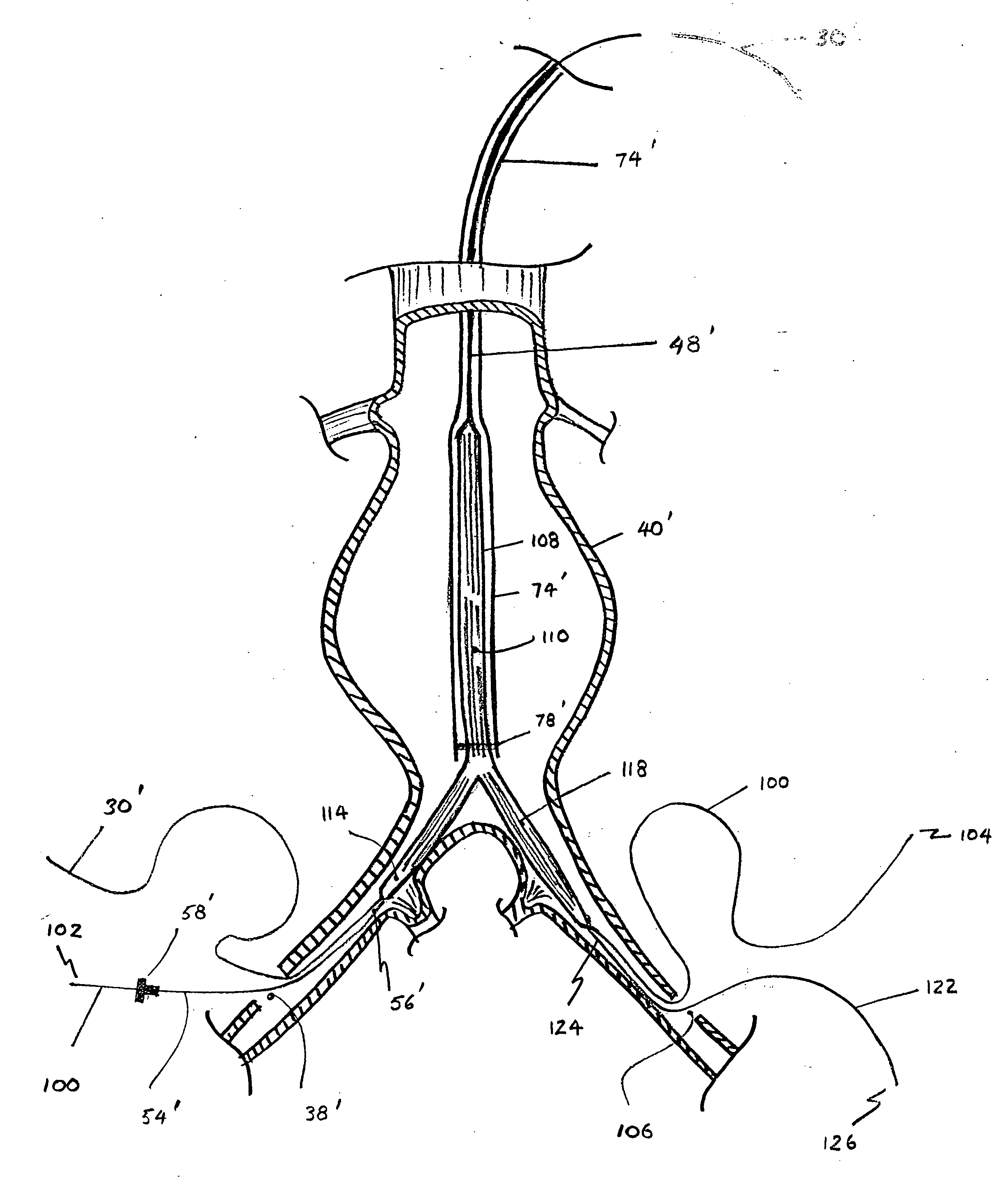
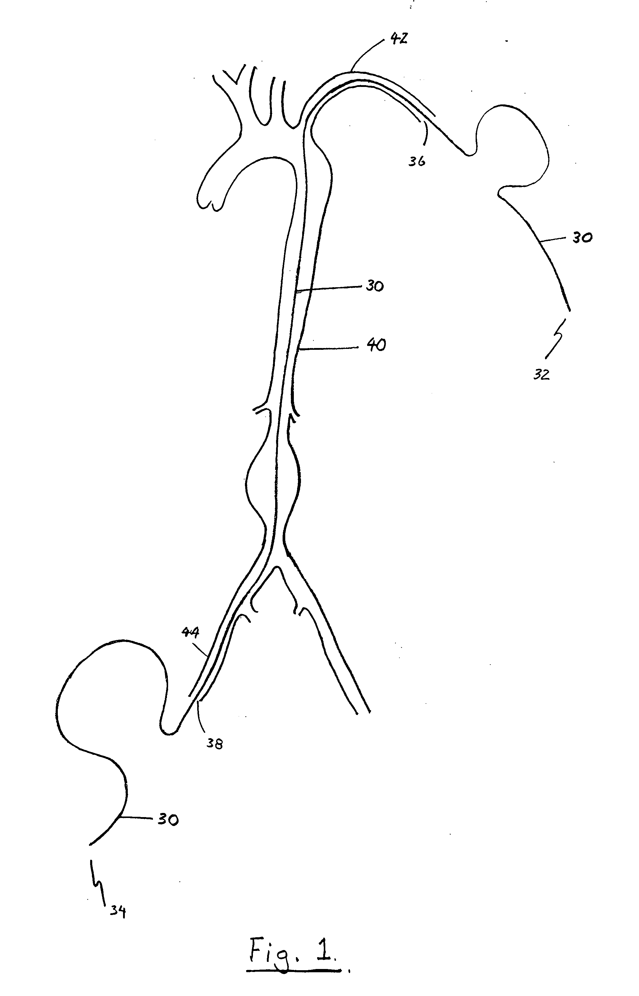
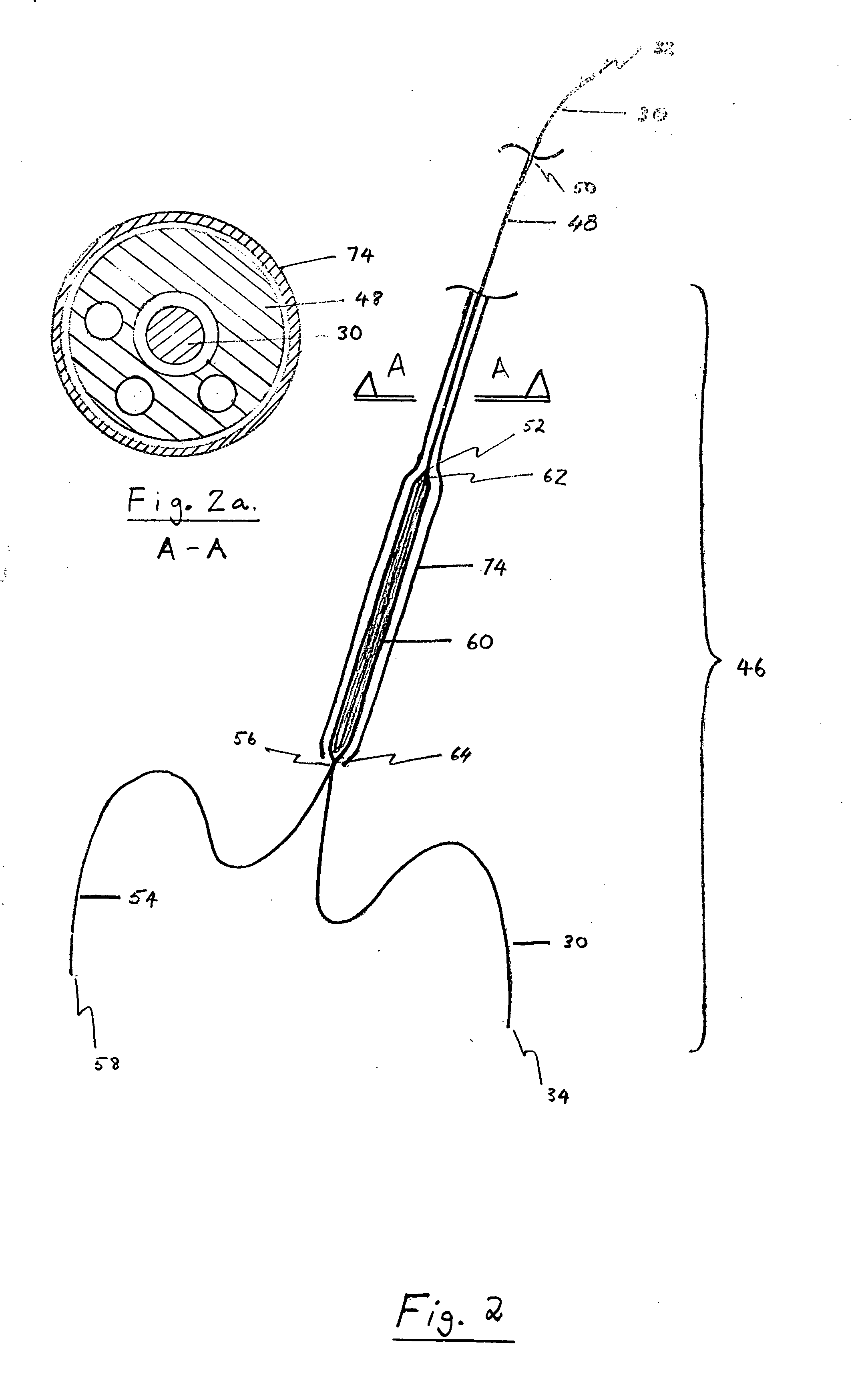
[0038] The device and method disclosed by the present invention may be used to deliver to a patient's vascular system a flexible tubular graft which may be straight, tapered, or bifurcated. In the preferred embodiment of this invention, the graft may be delivered to the patient's vascular system without performing surgery on the patient to open the vessel prior to insertion of the graft; rather, insertion is achieved percutaneously over a guidewire using the Saldinger technique or with a small diameter introducer sheath. Alternatively, insertion is achieved by applying force to the skin and vessel of the patient with the tapered end of the repair assembly sufficient to gain direct entry into the vessel. This method of insertion is referred to herein as the “direct percutaneous” method of insertion.

[0039] The terms “superior” and “inferior” shall be used herein to have the same meaning as the terms “up” and “down” respectively and shall signify ends or directions which are towards a...


PUM


Abstract

A graft for repairing defects in arteries is formed from a flexible graft and at least one attachment system. A device and method is disclosed for implanting a graft within the vasculature of a patient, in which the graft is inserted into the patient at a different stage than the attachment systems, and which allows for direct percutaneous insertion of the graft and attachment systems. The method permits control over the position of the graft in the vasculature during the course of deployment of the graft and attachment systems by providing for traction forces to be applied to opposing ends of the graft.

Description

[0001] This application is a continuation-in-part of U.S. Provisional Application No. 60 / 157,985 filed Oct. 6, 1999.FIELD OF THE INVENTION [0002] The present invention relates to intraluminal grafts and their attachment systems which are used for repairing defects in vessels and other lumens within the body. More particularly, the present invention relates to systems for forming linear and bifurcated grafts and to methods for delivering such grafts and their attachment systems to the correct position within the defective body lumen by staged implantation. BACKGROUND OF THE INVENTION [0003] Aneurysms are discrete dilations of the arterial wall. One of the most common, and among the most life threatening, is an aneurysm of the abdominal aorta between the renal and iliac arteries. If untreated, the aneurysm dilates progressively with an ever increasing risk of rupture and hemorrhagic death. [0004] One method of treatment is provided by direct surgical intervention, in which the defecti...

Claims


Application Information

Patent Timeline
Patent Type & Authority Applications(United States)
IPC IPC(8): A61F2/06
CPCA61F2/07A61F2/95A61F2002/065A61F2002/075A61F2220/0016A61F2/848A61F2/89A61F2220/0008Y10S623/903
Inventor CHUTER, TIMOTHY A.M.
Owner COOK INC
Learn More