

Electronic control unit having hold circuit and method therefor
- Summary
- Abstract
- Description
- Claims
- Application Information
AI Technical Summary
Benefits of technology
Problems solved by technology
Method used
Image

Examples
first embodiment
[0036] (First Embodiment)
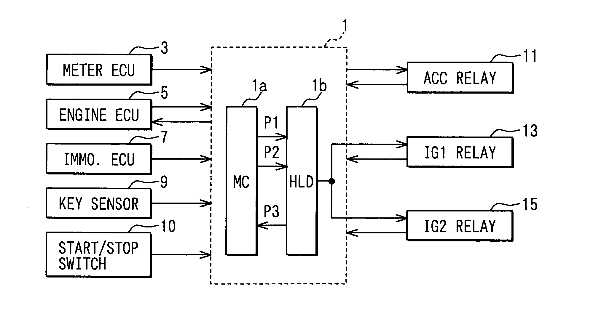
[0037] Referring first to FIG. 1, an in-vehicle power supply control system comprises: a power supply electronic control unit (ECU) 1 which is installed in the vehicle; a meter ECU 3, an engine ECU 5, and an immobilizer ECU 7 which are connected with the power supply ECU 1; a key sensor 9 for inserting a card key (not shown); a start / stop switch 10 which is a pushbutton switch for inputting commands instructing start or stop of power supply; an accessory (ACC) relay 11; a first ignition (IG1) relay 13; and a second ignition (IG2) relay 15. The relays 11, 13 and 15 are controlled objects.
[0038] The meter ECU 3 is for displaying on a display unit varying status of the vehicle, including vehicle speed, engine speed, opening / closing of doors, and the shift range of a transmission device. The meter ECU 3 outputs vehicle speed information to the power supply ECU 1.
[0039] The engine ECU 5 is an engine controller which controls an engine, and outputs engine speed ...
second embodiment
[0074] (Second Embodiment)
[0075] A power supply system 21 in the second embodiment is so designed as to control the state of passage of current through the feeder lines installed for supplying power to various in-vehicle devices mounted in vehicles.
[0076] As illustrated in FIG. 4, the power supply system 21 comprises: a pushbutton switch 23 for manually inputting commands instructing start or stop of power supply; a microcomputer 25 which has a port for outputting a hold pulse signal (a train of a plurality of pulses) P1 and a port for outputting a cancel pulse signal (a train of a plurality of pulses) P2 as well, and operates to alternately output the signals P1 and P2 each time the pushbutton switch 23 is pressed; and an electronic control unit (ECU) 27 which changes the state of supply of a driving current Id to a driving coil of a relay RLY 20 connected in series with an electric power feeder line L according to the hold pulse signal P1 or the cancel pulse signal P2 from the mi...
third embodiment
[0098] (Third Embodiment)
[0099] A power supply system 21 in the third embodiment is different from the power supply system 21 in the second embodiment only in part of the configuration of an ECU 27.
[0100] As illustrated in FIG. 6, the ECU 27 in the power supply system 21 comprises in addition to the driving current supply circuit 215; a first counter 221 which counts the number of pulses of hold pulse signal P1 outputted from the microcomputer 25 and generates the hold trigger signal T1 when the count reaches a preset value; a second counter 223 which counts the number of pulses of the cancel pulse signal P2 outputted from the microcomputer 25 and outputs the cancel trigger signal T2 when the count reaches a preset value; a free-run timer 225 which operates in accordance with system clock CLK, and periodically generates a reset signal RST for resetting the counters 221 and 223 each time a certain period has passed; and an RS flip-flop circuit 227 which supplies a driving signal to ...
PUM
 Abstract
Description
Claims
Application Information