Synchronous rectification chip temperature detection control device and method

A synchronous rectification, detection and control technology, applied in emergency protection circuit devices, electrical components, etc., can solve the problems of limited body diode current capacity, cause fire, safety hazards, etc., to avoid frequent actions, low cost, and strong practicability. Effect

Active Publication Date: 2020-08-04
WUXI YINGNUOPUSI MICROELECTRONICS
View PDF10 Cites 0 Cited by
  • Summary
  • Abstract
  • Description
  • Claims
  • Application Information

AI Technical Summary

Problems solved by technology

In fact, when the temperature is detected to be too high, it just turns off timing detection and driving. However, the primary main control chip does not know that the temperature of the chip on the secondary side is high, the output voltage still exists, and the load is still working. At this time, the synchronization The body diode of the power tube inside the rectifier chip will continue to work instead of the power MOSFET, and the current capacity of the body diode is limited and will not be disconnected. As the temperature rises, it will eventually cause burnout, and may even cause Fire, a serious safety hazard

Method used


Image

  • Synchronous rectification chip temperature detection control device and method
  • Synchronous rectification chip temperature detection control device and method
  • Synchronous rectification chip temperature detection control device and method

Examples


Embodiment Construction

[0023] In order to facilitate the understanding of the present invention, the present invention will be described more fully below with reference to the associated drawings. Preferred embodiments of the invention are shown in the accompanying drawings. However, the present invention can be embodied in many different forms and is not limited to the embodiments described herein. On the contrary, the purpose of providing these embodiments is to make the disclosure of the present invention more thorough and comprehensive. It should be noted that when an element is considered to be "connected" to another element, it may be directly connected to the other element or there may be intervening elements at the same time. Unless otherwise defined, all technical and scientific terms used herein have the same meaning as commonly understood by one of ordinary skill in the technical field of the invention. The terms used herein in the description of the present invention are for the purpos...


PUM


Abstract

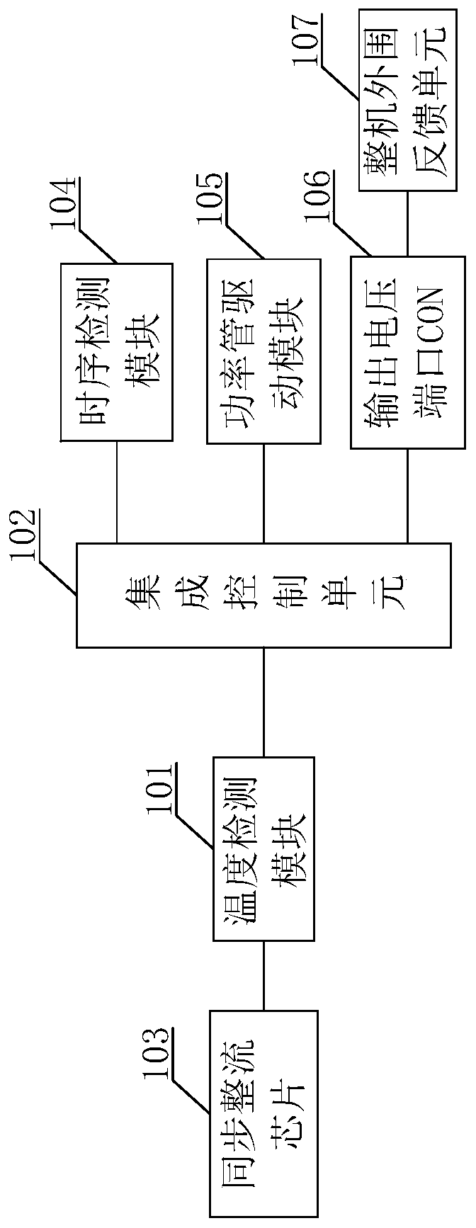
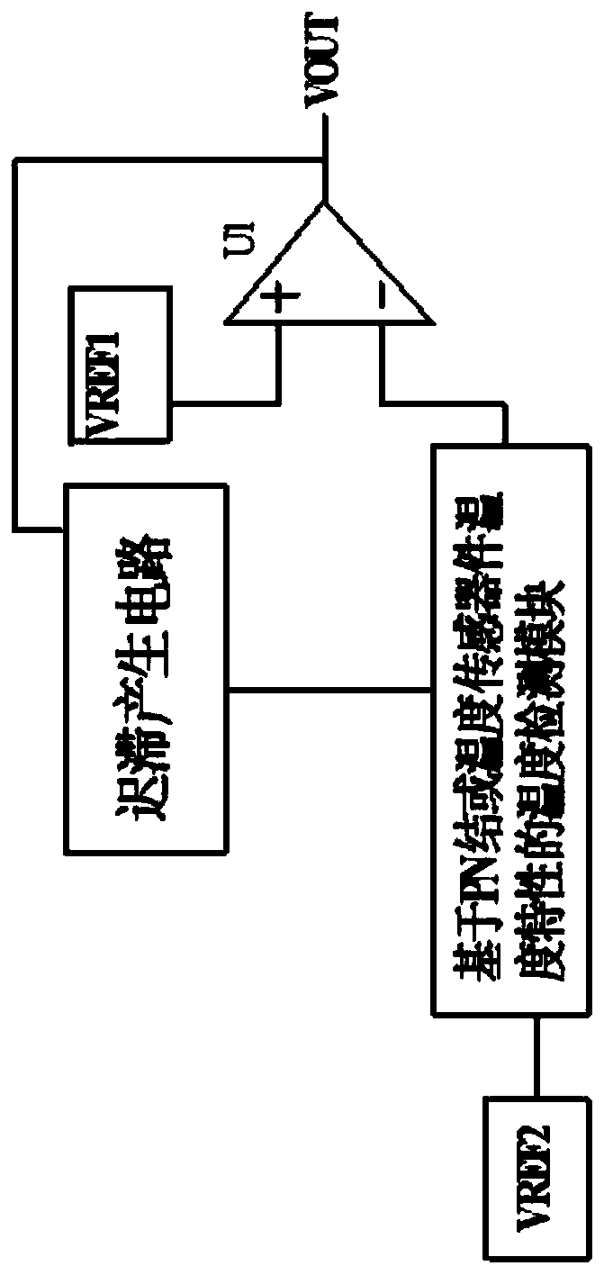
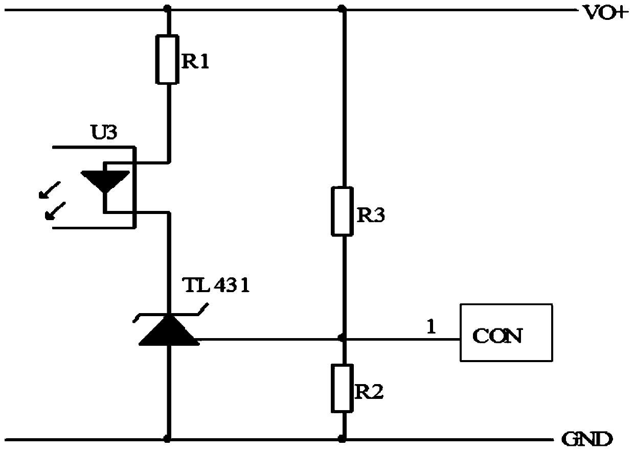
The invention discloses a synchronous rectification chip temperature detection control device and method. The device comprises a temperature detection module and an integrated control module. The temperature detection module is used for sampling the temperature of the synchronous rectification chip and converting the temperature into an electric signal; the integrated control module is used for controlling a time sequence detection module to stop time sequence detection when the temperature of the synchronous rectification chip is abnormal, controlling a power tube driving module to stop powerdriving, and outputting a signal to a complete machine peripheral feedback unit through the output voltage port CON to reduce output voltage. The complete machine load power under the condition thatthe temperature of the synchronous rectification chip is abnormal can be effectively reduced, and the reliability and safety of a power supply system are ensured.

Description

technical field [0001] The invention relates to the technical field of microelectronic detection, in particular to a synchronous rectification chip temperature detection and control device and method. Background technique [0002] Synchronous rectification technology is a new technology that uses special power MOSFET with extremely low on-state resistance to replace Schottky diode to reduce rectification loss. At present, mainstream chips on the market generally have an internal over-temperature protection function. When the temperature is too high, the drive of the synchronous rectification chip will be stopped. When the abnormality is resolved, the synchronous timing detection function will be turned on normally. In fact, when the temperature is detected to be too high, it just turns off timing detection and driving. However, the primary main control chip does not know that the temperature of the chip on the secondary side is high, the output voltage still exists, and the ...

Claims


Application Information

Patent Timeline
Patent Type & Authority Applications(China)
IPC IPC(8): H02H7/122
CPCH02H7/1225
Inventor 沈西琪顾松山
Owner WUXI YINGNUOPUSI MICROELECTRONICS
Why Eureka
Try Eureka