
Drive control system

A drive control and drive unit technology, applied in the direction of output power conversion devices, electrical components, etc., can solve the problems of not being able to drive MOSFETs, etc., and achieve the effects of avoiding severe heat generation, fast turn-on and turn-off speed, and stable output

Active Publication Date: 2020-07-21
HELLA SHANGHAI ELECTRONICS
View PDF5 Cites 0 Cited by
  • Summary
  • Abstract
  • Description
  • Claims
  • Application Information

AI Technical Summary

Problems solved by technology

Currently commonly used drive circuits include totem-pole circuits, quasi-totem-pole circuits, and upgrade circuits based on NMOS tubes, but these circuits cannot efficiently and stably drive MOSFETs in various application scenarios such as low-voltage input, wide-voltage input, and dual-voltage input. , unable to make the field effect tube play a role stably to promote the next stage

Method used


Image

  • Drive control system
  • Drive control system
  • Drive control system

Examples


Embodiment Construction

[0042] The advantages of the present invention will be further elaborated below in conjunction with the accompanying drawings and specific embodiments.

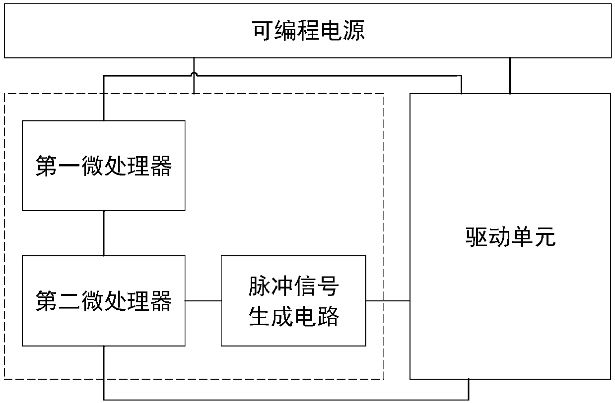
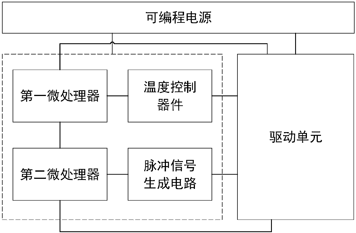
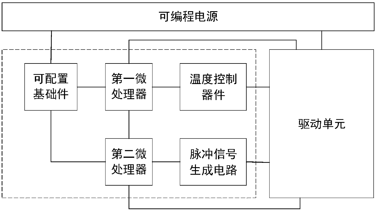
[0043] See attached figure 1It is a structural diagram of a drive control system according to a preferred embodiment of the present invention. The drive control system includes a programmable power supply, a control unit and a drive unit connected to the programmable power supply. Among them, the programmable power supply inputs a custom signal to supply power to the control unit and the drive unit, the control unit is connected to the drive unit, the control unit outputs a pulse control signal to the input terminal of the drive unit, and the input terminal of the drive unit receives the pulse control signal to work Drive the MOSFET, the MOSFET is a PMOS tube or NMOS tube, and the MOSFET continues to promote the work of the next stage of the circuit. Wherein, the control unit includes a first microprocessor, a second micropr...


PUM


Abstract

The invention provides a drive control system. The system comprises a programmable power supply, and a control unit and a driving unit which are connected with the programmable power supply, wherein the programmable power supply supplies power to the control unit and the driving unit, the control unit is connected with the driving unit, the control unit outputs a pulse control signal to the inputend of the driving unit, and the input end of the driving unit receives the pulse control signal to work and drives a next-stage circuit; the control unit comprises a first microprocessor, a second microprocessor and a pulse signal generation circuit. After the technical scheme is adopted, the technical problem that the high-power field effect transistor driving circuit is connected with the output when a programmable power supply is used for input at low voltage can be effectively solved, so that the MOS transistor at the high-voltage side can be effectively controlled at the low-voltage side, and meanwhile, the MOS transistor at the high-voltage side can effectively and stably drive the next stage of circuit.

Description

technical field [0001] The invention relates to the field of drive control, in particular to a drive control system. Background technique [0002] MOSFET has many advantages such as fast switching speed, good conduction performance, high integration, high flexibility, and rich application scenarios, so it is widely used in digital circuits and analog circuits. MOSFET needs a driving circuit to drive its work, and the driving circuit The stability of the MOSFET directly affects the performance of the MOSFET. Currently commonly used drive circuits include totem-pole circuits, quasi-totem-pole circuits, and upgrade circuits based on NMOS tubes, but these circuits cannot efficiently and stably drive MOSFETs in various application scenarios such as low-voltage input, wide-voltage input, and dual-voltage input. , It is impossible to make the field effect tube play a role stably and promote the next stage. Therefore, how to make the MOSFET function efficiently and stably in vario...

Claims


Application Information

Patent Timeline
Patent Type & Authority Applications(China)
IPC IPC(8): H02M1/08
CPCH02M1/08
Inventor 洪智铭
Owner HELLA SHANGHAI ELECTRONICS
Learn More