System and method for adaptive flow control

Active Publication Date: 2005-02-10
AVAGO TECH INT SALES PTE LTD
View PDF7 Cites 5 Cited by
  • Summary
  • Abstract
  • Description
  • Claims
  • Application Information

AI Technical Summary

Benefits of technology

[0010] Embodiments of the invention provide a system and method for controlling resource usage in a network switching system by transmitting pause off packets to network nodes after a calculated time based on resource usage measurements. Advantages of the system and method include increasing the utilization of the network switching system by limiting traffic from network nodes causing congestion; improving fairness since the system and method work for unicast, multicast and broadcast packets by ignoring the type of packet; and simplifies pause off / on logic by eradicating asynchronous loopback logic.

Problems solved by technology

However, in certain circumstances the network switching systems may not be able to instantaneously route traffic to a certain node.
For example, if several nodes are transmitting data to a single node, a network switching system may become overloaded with respect to that one node.
However, these queues can also become overloaded.
When network switching system queues and other network switching system resources become congested according to a resource usage measurement, conventional network switching systems transmit pause on packets to the networks nodes that are causing the congestion because of excessive packet transmission.
However, because the pause on and pause off packets are transmitted based on only sequential resource usage measurements, the pause on and off conditions tend to cycle back and forth rapidly, thereby not fully alleviating the congestion condition or not alleviating the congestion condition for any meaningful amount of time.
Further, conventional network switching systems only measure resource congestion as it relates to unicast packets.
An additional drawback of conventional switching systems is that they use asynchronous loopback logic, which can cause complications because the underpinning of network switching systems is generally based on synchronous design.

Method used


Image

  • System and method for adaptive flow control
  • System and method for adaptive flow control
  • System and method for adaptive flow control

Examples


Embodiment Construction

[0019] The following description is provided to enable any person having ordinary skill in the art to make and use the invention, and is provided in the context of a particular application and its requirements. Various modifications to the embodiments will be readily apparent to those skilled in the art, and the generic principles defined herein may be applied to other embodiments and applications without departing from the spirit and scope of the invention. Thus, the present invention is not intended to be limited to the embodiments shown, but is to be accorded the widest scope consistent with the principles, features and teachings disclosed herein.

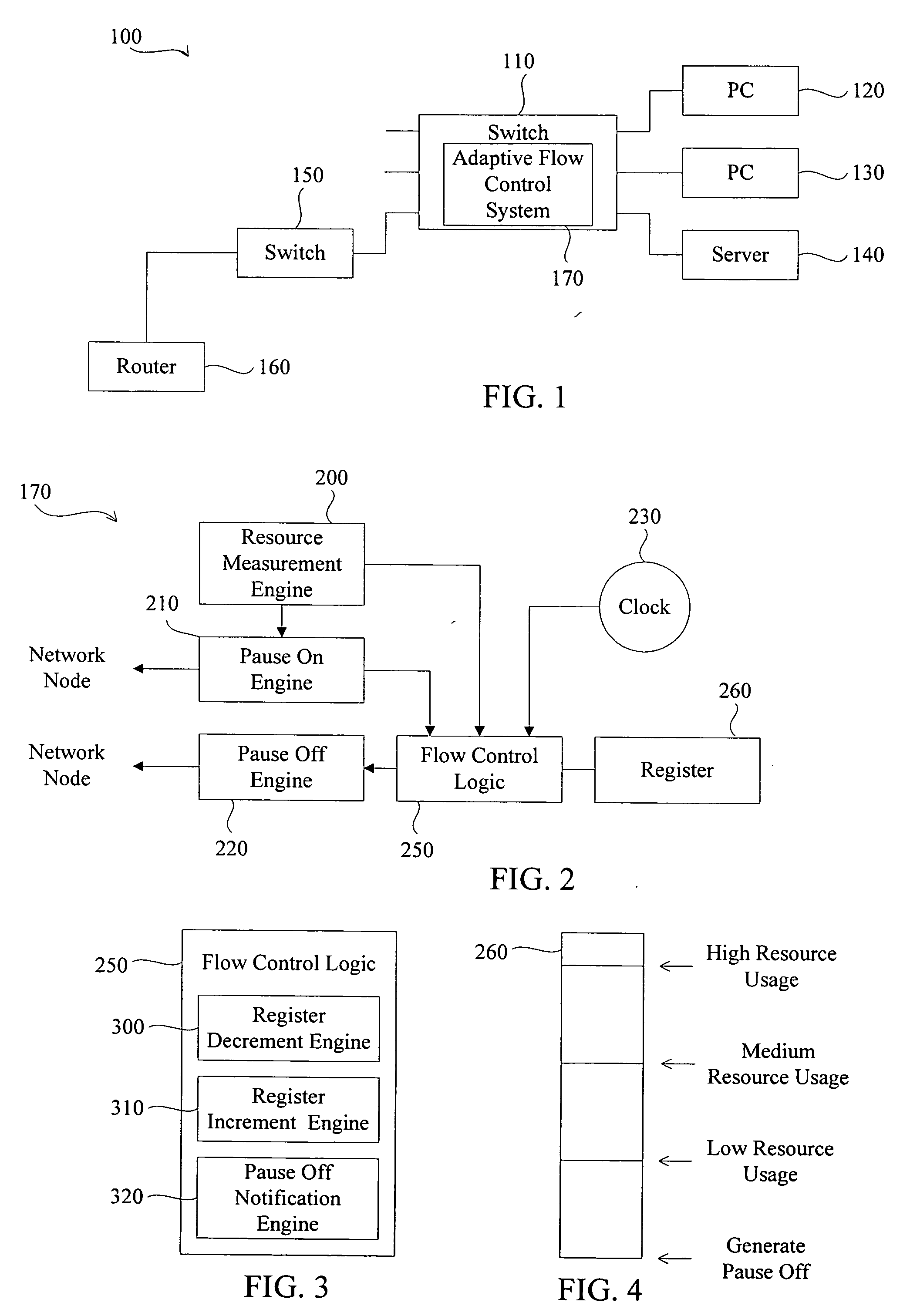
[0020]FIG. 1 is a block diagram illustrating a network system 100 in accordance with an embodiment of the present invention. The network system 100 includes 6 nodes: PCs 120 and 130, a server 140, a switch 110, a switch 150, and a router 160. The switch 150, the PC 120 and 130, and the server 140 are each communicatively coupled, via wi...


PUM


Abstract

The system and method for adaptive flow control transmits pause off packets to network nodes after a calculated time based on switch resource usage thereby alleviating congestion is a network switching system.

Description

PRIORITY REFERENCE TO PRIOR APPLICATION [0001] This application claims benefit of and incorporates by reference U.S. Patent application No. 60 / 492,986, entitled “Adaptive Flow Control,” filed on Aug. 7, 2003, by inventor Jiann-Jyh (James) Lay.BACKGROUND OF THE INVENTION [0002] 1. Technical Field [0003] This invention relates generally to switches, and more particularly, but not exclusively, to a system and method for adaptively controlling traffic flow within a network system to limit network switching system congestion. [0004] 2. Description of the Related Art [0005] Networks, such as local area networks (i.e., LANs) and wide area networks (i.e., WANs, e.g., the Internet), enable a plurality of nodes to communicate with each other. Nodes can include computers, servers, storage devices, mobile devices, PDAs, wireless telephones, etc. Networks can include the nodes themselves, a connecting medium (wired, wireless and / or a combination of wired and wireless), and network switching syst...

Claims


Application Information

Patent Timeline
IPC IPC(8): G01L7/00H04L12/56
CPCH04L49/506
Inventor LAY JIANN-JYH (JAMES)
Owner AVAGO TECH INT SALES PTE LTD
Why Eureka
Try Eureka