
Beamforming and distributed opportunistic scheduling in wireless networks

a wireless network and beamforming technology, applied in the field of wireless networking, can solve the problems of existing systems, inability to properly deliver packets, and limitations due to fixed amount of resources available, and routing protocols would not be able to do so

Inactive Publication Date: 2010-06-01
TELCORDIA TECHNOLOGIES INC +1
View PDF10 Cites 32 Cited by
  • Summary
  • Abstract
  • Description
  • Claims
  • Application Information

AI Technical Summary

Benefits of technology

[0037]The preferred embodiments of the present invention can significantly improve upon existing methods and / or apparatuses.
[0039]According to some embodiments, a novel system architecture is presented that enables Wireless Local Area Network (WLAN) devices and networks to achieve improved performance by opportunistic exploitation of induced channel variations. Preferably, the system creates high channel variations using a beam-former at an Access Point (AP) and makes use of this induced channel variation using a distributed and opportunistic scheduling mechanism. In the preferred embodiments, the net result is a wireless system with significantly less collision probability leading to improvement in the throughput and energy consumption of the WLAN devices. This work shows how such a high efficiency technique can be implemented in future WLAN devices, within the framework of the current and proposed IEEE 802.11 WLAN standards.
[0043]In some embodiments, a system and method is provided that can improve throughput and / or energy consumption metrics for a WLAN in the infrastructure mode, while using a distributed contention based medium access scheme (such as, e.g., 802.11 DCF), in a manner that enhances fairness for the various users of the network.
[0044]According to some embodiments, a method for improving performance and / or energy utilization in a WLAN system is performed that includes: a) inducing fluctuations in signal strength transmitted from an access point to stations within a transmission range of the access point; and b) exploiting the induced fluctuations to make the stations channel aware and opportunistic.
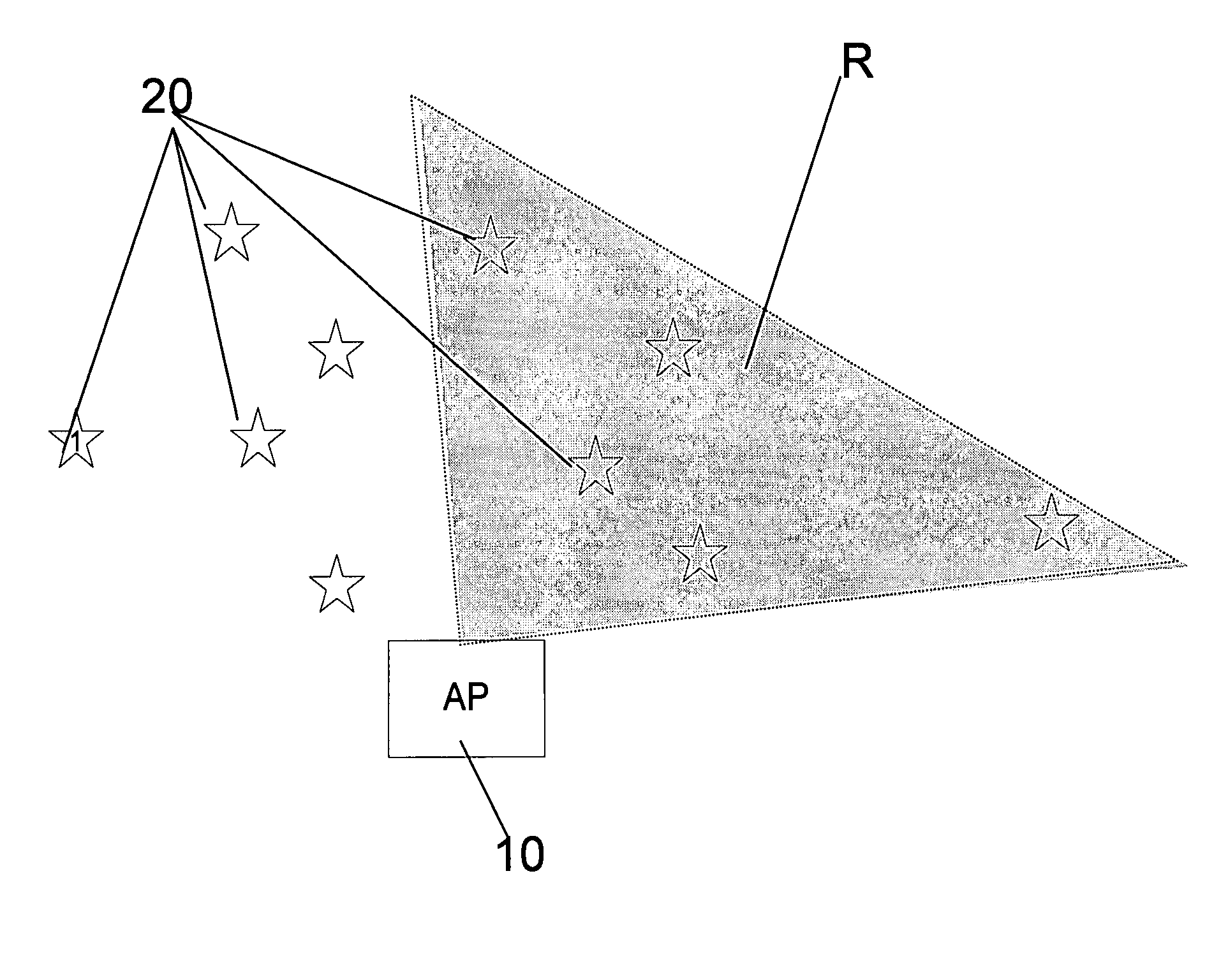
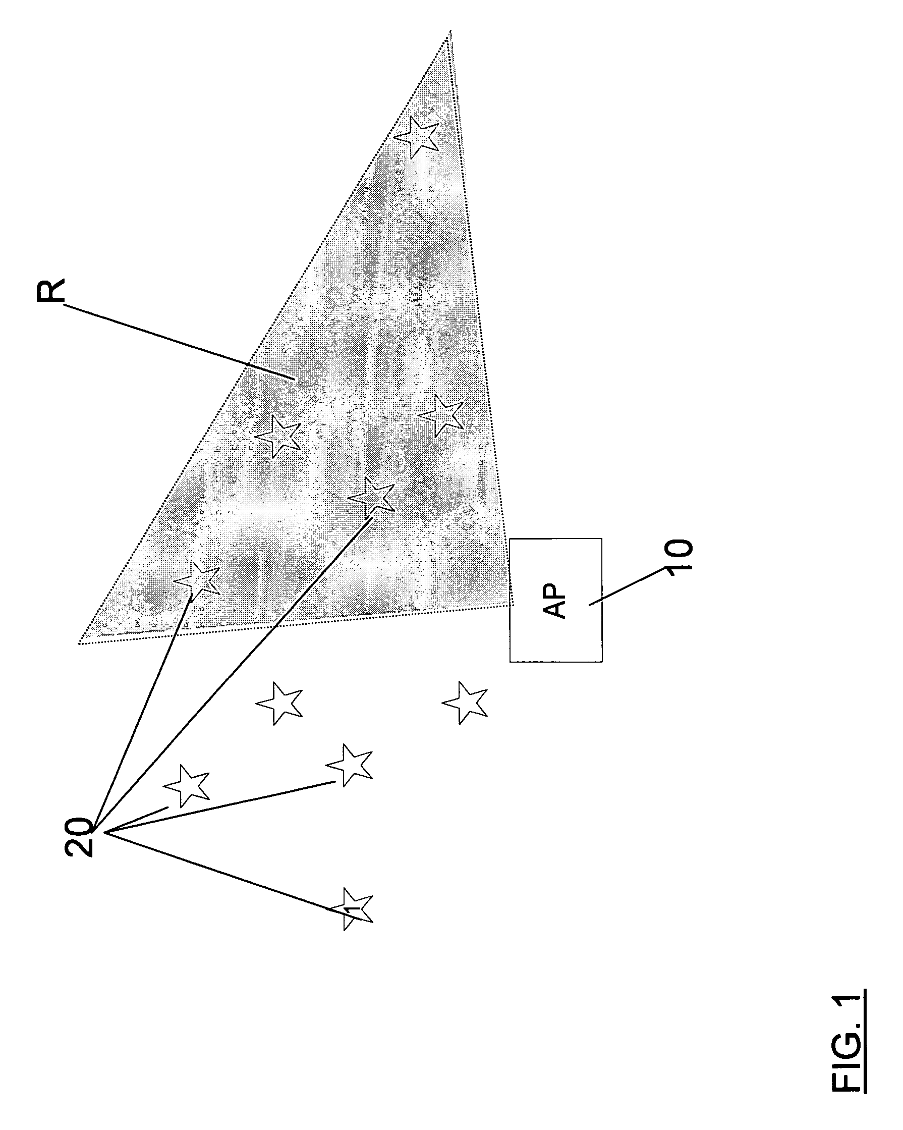
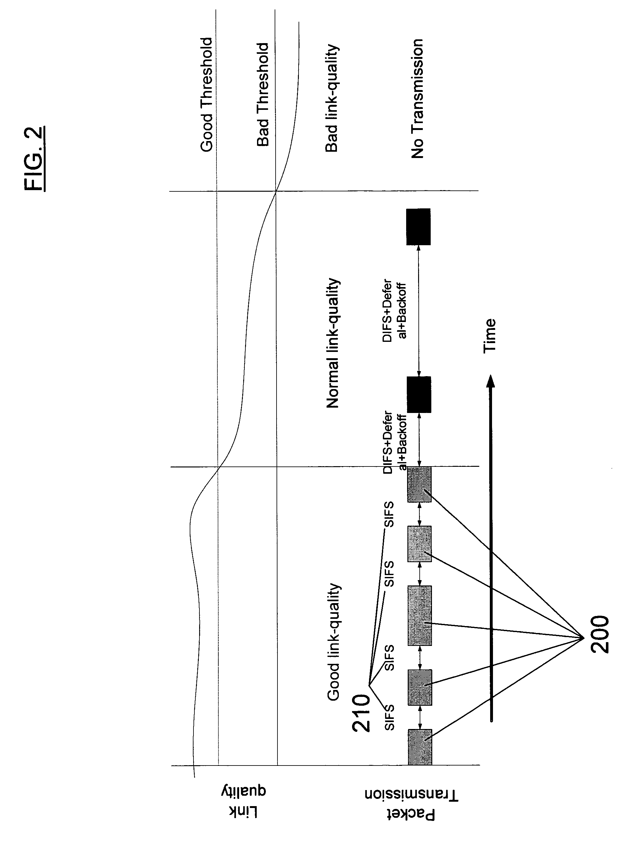
[0045]According to some embodiments, a system for enhancing the performance of a WLAN system is performed that includes: a) an access point having a variable beamformer configured to fluctuate signal strength as perceived by stations within a range of the access point; b) a plurality of stations having modified distributed-MAC protocol such as to be channel-aware and opportunistic. In some examples, the system further includes that the stations are configured to either transmit multiple back-to-back packets or to not contend for the medium based channel in response to variations from the variable beamformer. In some examples, the variable beamformer is configured to change a beamforming pattern to cover different stations at different time periods. In some examples, the beamformer creates a beamforming pattern such that stations inside of the beamforming pattern have a high link-quality and stations outside the beamforming pattern have poor link-quality. In some examples, the system is configured to categorize link quality at the stations and to opportunistically vary transmission based on the link quality.
[0048]According to some other embodiments, a method for enhancing a WLAN infrastructure system is performed that includes: using Distributed Opportunistic Scheduling (DOS) to exploit an access point radiation-beam induced multi-user diversity, providing variations in channel conditions among users, by transmitting back-to-back packets when channel conditions are favorable to reduce inter-transmission delays and by withholding transmission when channel conditions are unfavorable to reduce collision probability.

Problems solved by technology

Otherwise, routing protocols would not be able to deliver the packets properly.
Existing systems have a variety of limitations, including, e.g., limitations due to the fixed amount of resources available, such as, e.g., limitations on bandwidth and power.
The number of packets that can be transmitted back-to-back is inversely proportional to the current data rate, and this makes the system highly unfair from an individual throughput perspective.
The method does not apply to stations in a WLAN infrastructure system (which transmit packet only to the AP), and hence fails to give high throughput gains in an infrastructure mode system.

Method used


Image

  • Beamforming and distributed opportunistic scheduling in wireless networks
  • Beamforming and distributed opportunistic scheduling in wireless networks
  • Beamforming and distributed opportunistic scheduling in wireless networks

Examples


Embodiment Construction

[0037]The preferred embodiments of the present invention can significantly improve upon existing methods and / or apparatuses.

[0038]According to the preferred embodiments, systems and methods are provided that address the issue of inducing and exploiting multi-user diversity in, e.g., a WLAN system in a substantially fully distributed and opportunistic manner.

[0039]According to some embodiments, a novel system architecture is presented that enables Wireless Local Area Network (WLAN) devices and networks to achieve improved performance by opportunistic exploitation of induced channel variations. Preferably, the system creates high channel variations using a beam-former at an Access Point (AP) and makes use of this induced channel variation using a distributed and opportunistic scheduling mechanism. In the preferred embodiments, the net result is a wireless system with significantly less collision probability leading to improvement in the throughput and energy consumption of the WLAN de...


PUM


Abstract

A system and method that addresses the issue of inducing and exploiting multi-user diversity in, e.g., a WLAN system in a fully distributed and opportunistic manner. In some embodiments, the system includes: an access point having a variable beamformer configured to fluctuate signal strength as perceived by stations within a range of the access point; and a plurality of stations having modified distributed-MAC protocol such as to be channel-aware and opportunistic.

Description

BACKGROUND[0001]1. Field of the Invention[0002]The present application relates to wireless networking and, in some preferred embodiments, to systems and methods of performance enhancement of wireless local area networks and, in some preferred embodiments, to beamforming and opportunistic scheduling in wireless networks and / or the like.[0003]2. General Background Discussion:[0004]Networks and Internet Protocol[0005]There are many types of computer networks, with the Internet having the most notoriety. The Internet is a worldwide network of computer networks. Today, the Internet is a public and self-sustaining network that is available to many millions of users. The Internet uses a set of communication protocols called TCP / IP (i.e., Transmission Control Protocol / Internet Protocol) to connect hosts. The Internet has a communications infrastructure known as the Internet backbone. Access to the Internet backbone is largely controlled by Internet Service Providers (ISPs) that resell acces...

Claims


Application Information

Patent Timeline
Patent Type & Authority Patents(United States)
IPC IPC(8): H04W4/00H04W72/12H04W80/02H04W84/12H04W88/08
CPCH04B7/0617H04B7/0452H04W88/08H04W80/02H04W84/12H04W72/1257H04W72/535
Inventor GOPALAKRISHNAN, PRAVEENFAMOLARI, DAVIDOBAYASHI, SHUICHIYAQUB, RAZIQ
Owner TELCORDIA TECHNOLOGIES INC
Learn More