
Eureka
For R&D, Eureka makes reading and utilizing patents & technical documents easy.
Eureka AIR
Designed for self-driven R&D workflows. Generate viable solutions, solve complex R&D challenges, empower your innovation with AI.

Eureka Materials
Designed for material experts only. Revolutionize your material R&D, from search, analyze, to developing new materials.

TechResearch
Generate reliable direction feasibility study reports for your R&D in just a few steps.

TechSeek
Discover and master advanced knowledge NOW. Basics, ideas, possibilities, all at once.

TechMind
As an expert in R&D Theories, TechMind can generates customized viable solutions instantly.

TechRisk
Analyze your overall solution with one click, know your potential R&D risks in advance.

TechMonitor
Get weekly tech updates, stay abreast of the latest tech innovations and key insights.
Receiving apparatus and receiving method
- Summary
- Abstract
- Description
- Claims
- Application Information
AI Technical Summary
Benefits of technology
Problems solved by technology
Method used
Image

Examples
first embodiment
[0067] (First Embodiment)
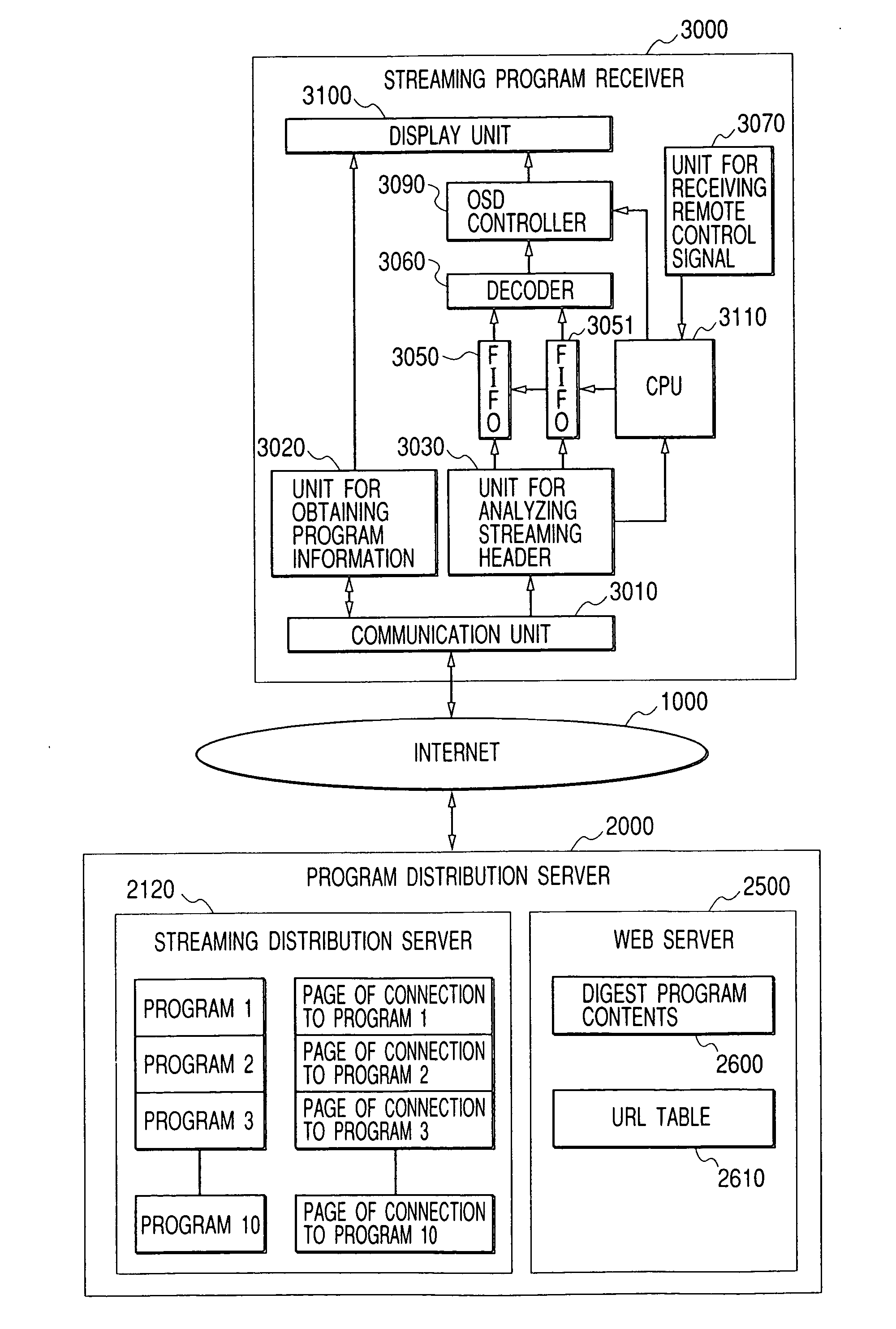
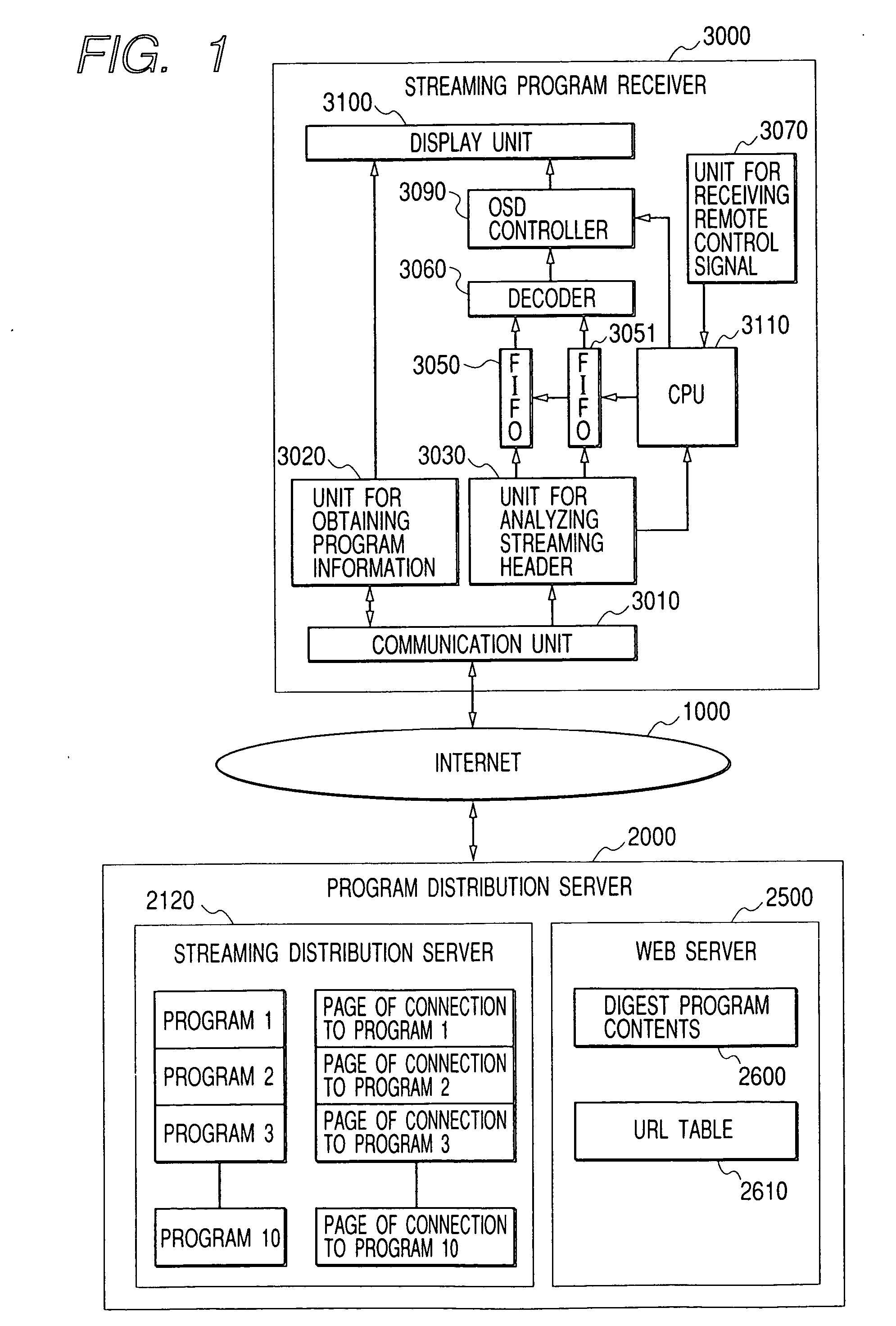
[0068] A streaming program distribution system according to the first embodiment to which the invention is applied will be described hereinbelow with reference to the drawings. FIG. 1 is a diagram showing a construction of a main section of the streaming program distribution system in the first embodiment.
[0069] In FIG. 1, reference numeral 1000 denotes an Internet for transmitting streaming program data, program information, and the like. Reference numeral 2000 denotes a program distribution server for executing accumulation, storage, transmission, and the like of streaming program contents, program information, and the like. The program distribution server 2000 comprises: a streaming distribution server 2100 for distributing a streaming program to a streaming program receiver; and a WEB server 2500 for distributing the program information to the streaming program receiver.
[0070] The streaming program data constructed by a video image and an audio sound h...
second embodiment
[0109] (Second embodiment)
[0110] A streaming program distribution system according to the second embodiment to which the invention is applied will be described hereinbelow. A construction of a main section of the streaming program distribution system in the second embodiment is similar to that of FIG. 1 and different portions will be explained hereinbelow.
[0111] The streaming program receiver 3000 in the second embodiment is shown in FIG. 14. In the diagram, reference numerals 3050 to 3053 denote FIFOs and these FIFOs are different from the FIFOs in the first embodiment.
[0112] In the construction of FIG. 14, the operations which are executed until the streaming program receiver 3000 requests the HTML document on the portal display screen from the program distribution server 2000 and finally displays the digest program contents 2600 onto the display unit 3100 are similar to those in the first embodiment.
[0113] Subsequently, the operation of the WEB server 2500 will be described.
[...
third embodiment
[0140] (Third Embodiment)
[0141] Subsequently, the third embodiment will be described.
[0142] A construction of a main section of the streaming program distribution system in the third embodiment is similar to that of the second embodiment and different portions will be explained hereinbelow.
[0143] In the third embodiment, the operations which are executed until the streaming program receiver 3000 requests the HTML document on the portal display screen from the program distribution server 2000 and finally displays the digest program contents 2600 onto the display unit 3100, the data of the program 1 is buffered into the FIFO 3051, the data of the program 2 is buffered into the FIFO 3052, and the data of the program 3 is buffered into the FIFO 3053, that is, the operations which are executed until a state shown in FIG. 19 are similar to those in the second embodiment.
[0144] In FIG. 19, when the user operates the reservation button on the remote controller at a point of time “a” (cor...
PUM
 Abstract
Description
Claims
Application Information
 - R&D Engineer
- R&D Manager
- IP Professional
- Industry Leading Data Capabilities
- Powerful AI technology
- Patent DNA Extraction
Browse by: Latest US Patents, China's latest patents, Technical Efficacy Thesaurus, Application Domain, Technology Topic, Popular Technical Reports.
© 2024 PatSnap. All rights reserved.Legal|Privacy policy|Modern Slavery Act Transparency Statement|Sitemap|About US| Contact US: help@patsnap.com