
Time-extended cooling system for line-powered apparatus

a cooling system and line-powered technology, applied in the field of cooling systems, can solve the problems of dramatic temperature rise in the parts surrounding the hot component, inability to normalize the cooling cycle, and the heat generating component can get extremely hot, so as to prevent damage to electrical equipment

Inactive Publication Date: 2005-02-17
MITSUBISHI ELECTRIC RES LAB INC +1
View PDF9 Cites 31 Cited by
  • Summary
  • Abstract
  • Description
  • Claims
  • Application Information

AI Technical Summary

Benefits of technology

[0012] It is another objective of the invention to prevent damage to electrical equipment in the event of the loss of line power as caused by the stored heat of certain high temperature components.

Problems solved by technology

In some systems, the heat generating components can get extremely hot.
The temperature inside the component is often sufficient to destroy neighboring parts, unless the components are cooled.
This can cause a dramatic temperature rise in the parts surrounding the hot component, which can be destructive.
A severe problem arises if all power is lost unexpectedly, and a normal cool down cycle is not possible.
For video projectors, sudden loss of power and the resulting inability to properly cool the lamp results in a premature device failure.
A similar thermal problem occurs in an internal combustion engine, where heat must be dissipated after the engine has been turned off.
However, the system does not address cool down in the event of line power loss.
In this case, time keeping is the issue rather than thermal concerns.
Similarly, backup generators and uninterruptible power supplies are commonly used to keep computers and other vital equipment running during a power failure.

Method used


Image

  • Time-extended cooling system for line-powered apparatus
  • Time-extended cooling system for line-powered apparatus

Examples


Embodiment Construction

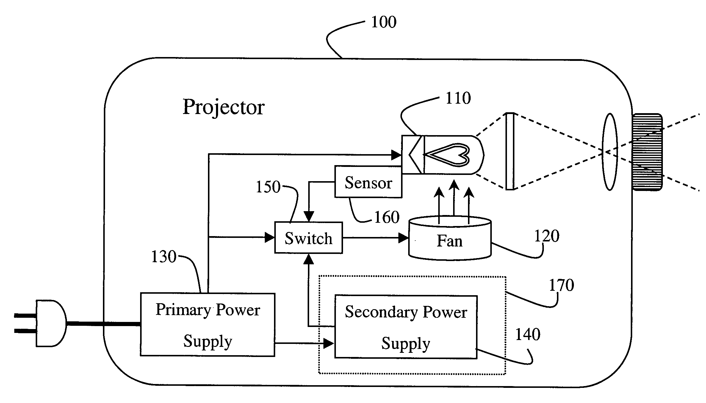
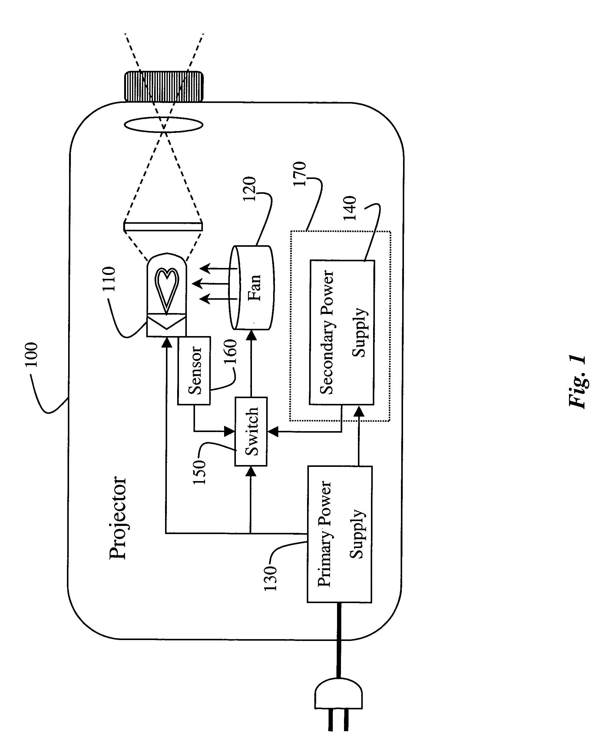
[0017]FIG. 1 shows a projector system 100 that uses the invention. It should be understood that the invention can also be used by other heat generating electrical systems and devices.

[0018] The projector includes a heat source 110, i.e., a lamp. The temperature of the lamp can reach several thousand degrees. If the lamp gets too hot, then it can self-destruct, as well as damage nearby components. Therefore, during normal operation, a fan 120 is used to cool the lamp. The fan is connected to a primary power supply 130, normally a power line.

[0019] In most modern projectors, the fan will continue to run for several minutes after the projector has been shut off to cool the lamp. However, should there be a failure in the power line, damage can still occur.

[0020] Therefore, the projector 100 also includes a secondary power supply 140, for example, a rechargeable battery. Should there be a failure in the primary power supply, then a switch 150 can cause the fan 120 to be operated from ...


PUM


Abstract

Certain electrical systems, such as projectors, contain components, which get very hot and require active cooling systems. During normal operation, a switch operates a cooling fan from a primary power supply. Upon detecting a failure in the primary power supply, the switch connects the cooling fan to a secondary power supply.

Description

FIELD OF THE INVENTION [0001] The present invention relates generally to cooling systems, and more particularly to line-powered electrical devices that generate heat. BACKGROUND OF THE INVENTION [0002] Many electrical devices and systems require active cooling systems to prevent over-heating. In passive cooling systems, the heat generated from internal components is conducted away to a cooler area via a path of sufficiently low thermal resistance. If the thermal resistance is too high or if the temperature difference is too small to support sufficient heat flow, active cooling systems must be employed. Forced air-cooling is often used for this purpose. It effectively lowers the thermal resistance, and thus lowers the temperature rise with respect to ambient conditions for a given amount of thermal energy. [0003] In some systems, the heat generating components can get extremely hot. The temperature inside the component is often sufficient to destroy neighboring parts, unless the comp...

Claims


Application Information

Patent Timeline
IPC IPC(8): F21V29/02H04N5/74F25B21/02F25B27/00H05K7/20
CPCF21V29/02F21V29/30H04N9/3144F25B27/00F25D2700/16F25B21/02F21V29/56F21V29/67
Inventor DIETZ, PAUL H.LEIGH, DARREN L.
Owner MITSUBISHI ELECTRIC RES LAB INC
Learn More