

Evaporation source for deposition process and insulation fixing plate, and heating wire winding plate and method for fixing heating wire
a technology of evaporation source and deposition process, which is applied in the direction of vacuum evaporation coating, chemical vapor deposition coating, coating, etc., can solve the problems of reducing the opening of the shadow mask, the increase of the fabrication cost, and the cost of organic materials in a practical use. , to achieve the effect of improving the shadow effect of the shadow mask and the low material use ra
- Summary
- Abstract
- Description
- Claims
- Application Information
AI Technical Summary
Benefits of technology
Problems solved by technology
Method used
Image

Examples
first embodiment
[0063]FIG. 5 is a perspective view of a linear evaporation source for the fabrication of a thin organic semiconductor device according to the present invention, and FIG. 6 is a side sectional view of the linear evaporation source of FIG. 5.
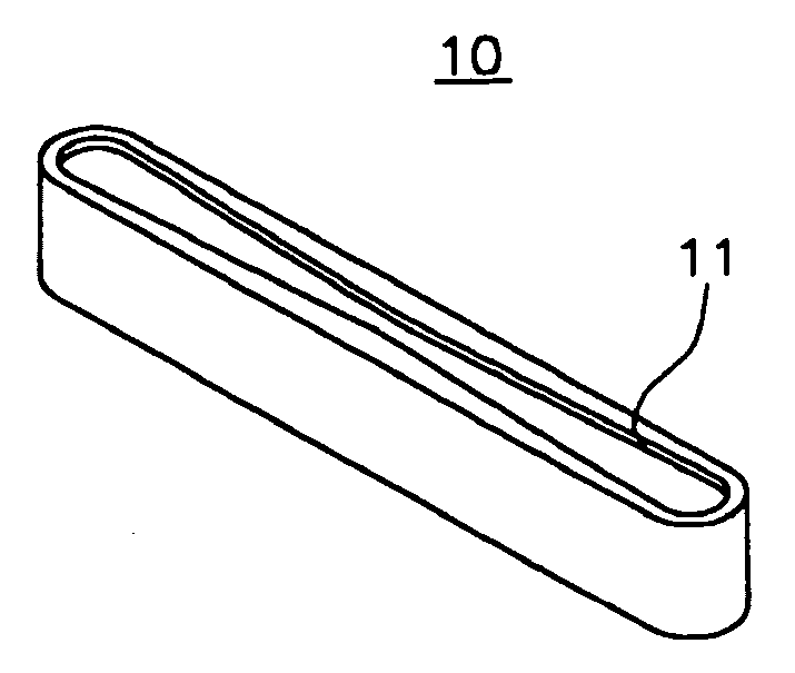
[0064] A crucible 10 has an opening 11 formed at one side thereof. The other side of the crucible 10 is closed to form a receiving space. A deposition material (A) is received in the receiving space. Preferably, the crucible 10 is shaped in a long cylinder, and the opening 11 is formed in the length direction of the crucible 10.
[0065] Hence, it is possible to deposit a thin film by moving a substrate in a direction normal to the length direction over the opening 11 or inversely moving the crucible 10.
[0066] According to the present invention, the width of the opening 11 is made to be narrow when it travels from the both ends of the crucible 10 to the center portion in the length direction, so that it becomes possible to deposit a thin film at a ...
second embodiment
[0071] Linear Evaporation Source
[0072] As shown in FIGS. 7a and 7b, an opening 11 is formed in a constant size in the length direction and an opening adjusting unit 20 having a nozzle section 21 of which width is the same in its shape as that of the first embodiment is separatably installed to enable an easy adjustment of the opening area.
[0073] Generally, since it is not easy to form an opening having the same shape as that of the first embodiment, the opening adjusting unit 20 is detachably fabricated and is attached to the opening 11 of the crucible 10.
[0074] The opening adjusting unit 20 can be fabricated integrally as one set or two or more openings can be separatably fabricated and installed in a combination. Preferably, a flange is formed at an upper end of the opening adjusting unit 20 so that it is possible to precisely set a depth closely inserted to the upper end of the crucible 10.
[0075] Also, a splashing preventive piece 30 is installed spaced by a constant distance ...
third embodiment
[0076] Linear Evaporation Source
[0077] In case the aforementioned second embodiment utilizes the opening adjusting unit 20, the opening adjusting unit 20 is inserted into the crucible 10 to function to shield heat so that relative temperature of the opening is lowered and thus the deposition material may be deposited on the opening adjusting unit 20. In such a case, while the deposition proceeds, there may be caused a result that the deposition material deforms the shape of the opening of the opening adjusting unit 20 and further closes the entrance.
[0078] To improve this drawback, as shown in FIG. 8, both side portions of the crucible 10 are partially dug to expose the opening adjusting unit 20 so that the exposed portion forms a heating section 12 to allow the heat of the heating wire upon deposition to heat the opening adjusting unit 20 directly and prevent the deposition material (A) from being deposited on the opening adjusting unit 20 and the entrance from being closed.
[0079...
PUM
| Property | Measurement | Unit |
|---|---|---|
| length | aaaaa | aaaaa |
| width | aaaaa | aaaaa |
| distance | aaaaa | aaaaa |
Abstract
Description
Claims
Application Information